Husqvarna ST131 Owners Manual - Page 6
Assembly
 |
View all Husqvarna ST131 manuals
Add to My Manuals
Save this manual to your list of manuals |
Page 6 highlights
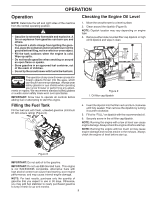
ASSEMBLY 2. Installing the Discharge Chute Procedure 1. Install the chute deflector to the discharge chute using bolts and, washer, nut, deflector knob and cap plunger (Figure 4). 2. Install the discharge chute to the chute base using three screws and nuts. 8 7 3. Installing the Upper Handle Cover 1. Install the upper handle cover to the handles using four screws (Figure 5). 54 10 3 9 1 6 3 2 2 Figure 4 1. Deflector 6. Discharge chute 2. Carriage bolts 3. Flange nuts 5/16-18 7. Carriage Bolt 8. Shoulder Bolt 4. Washer 9. Flange nuts 1/4-20 5. Knob 10. Cap Plunger IMPORTANT: Do not overtighten the flange nuts; otherwise you may damage the discharge chute. 1 2 Figure 5 1. Upper handle cover 2. Screws 6
-
 1
1 -
 2
2 -
 3
3 -
 4
4 -
 5
5 -
 6
6 -
 7
7 -
 8
8 -
 9
9 -
 10
10 -
 11
11 -
 12
12 -
13
-
14
-
15
-
16
-
17
-
18
-
19
-
20
-
21
-
22
-
23
-
24
-
25
-
26
-
27
-
28
 |
 |

6
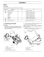
ASSEMBLY
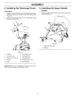
2. Installing the Discharge Chute
Procedure
1.
Install the chute deflector to the discharge chute using
bolts and, washer, nut, deflector knob and cap plunger
(Figure 4).
2.
Install the discharge chute to the chute base using
three screws and nuts.
IMPORTANT:
Do not overtighten the flange nuts; other-
wise you may damage the discharge chute.
Figure 4
1. Deflector
2. Carriage bolts
3. Flange nuts 5/16-18
4. Washer
5. Knob
6. Discharge chute
7. Carriage Bolt
8. Shoulder Bolt
9. Flange nuts 1/4-20
10. Cap Plunger
2
2
7
6
3
3
8
4
9
5
10
1
3. Installing the Upper Handle
Cover
1.
Install the upper handle cover to the handles using four
screws (Figure 5).
Figure 5
1. Upper handle cover
2. Screws
2
1