IBM 8307 Hardware Maintenance Manual - Page 52
illustration
 |
UPC - 087944816577
View all IBM 8307 manuals
Add to My Manuals
Save this manual to your list of manuals |
Page 52 highlights
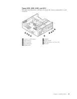
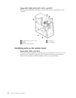
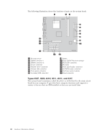
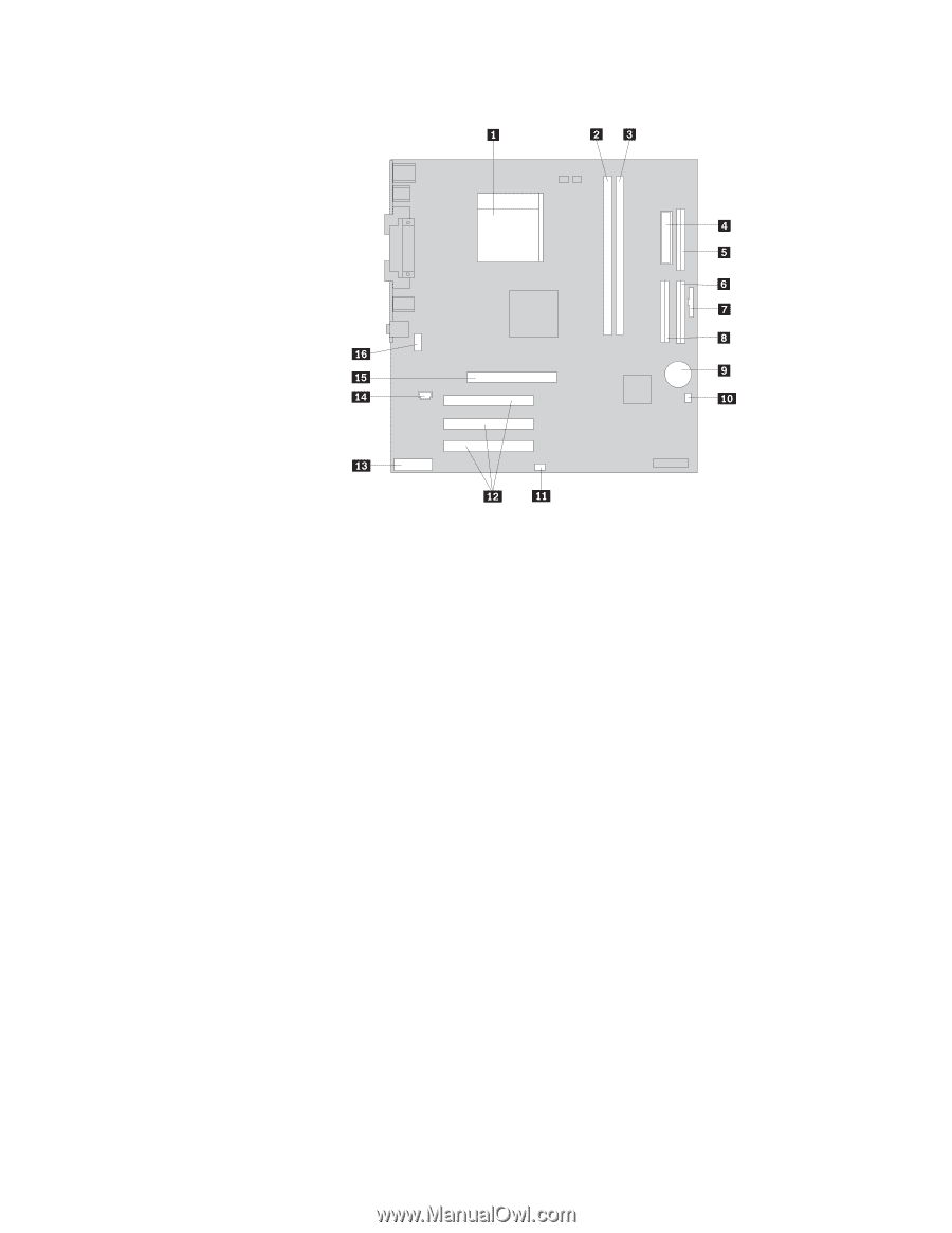
The following illustration shows the locations of parts on the system board. 1 Microprocessor 2 DIMM connector 1 3 DIMM connector 2 4 Power connector 5 Diskette drive connector 6 Primary IDE connector 7 Front panel connector 8 Secondary IDE connector 9 Battery 10 Clear CMOS/Recovery jumper 11 SCSI LED connector 12 PCI slots 13 Front panel audio connector 14 CD-ROM audio connector 15 AGP slot (some models) 16 Serial connector Types 8307, 8308, 8310, 8311, 8314, and 8315 The system board (sometimes called the planar or motherboard) is the main circuit board in your computer. It provides basic computer functions and supports a variety of devices that are IBM-installed or that you can install later. 46 Hardware Maintenance Manual
-
 1
1 -
2
-
3
-
4
-
5
-
6
-
7
-
8
-
9
-
10
-
11
-
12
-
13
-
14
-
15
-
16
-
17
-
18
-
19
-
20
-
21
-
22
-
23
-
24
-
25
-
26
-
27
-
28
-
29
-
30
-
31
-
32
-
33
-
34
-
35
-
36
-
37
-
38
-
39
-
40
-
41
-
42
-
43
-
44
-
45
-
46
-
 47
47 -
 48
48 -
 49
49 -
 50
50 -
 51
51 -
 52
52 -
 53
53 -
 54
54 -
 55
55 -
 56
56 -
 57
57 -
58
-
59
-
60
-
61
-
62
-
63
-
64
-
65
-
66
-
67
-
68
-
69
-
70
-
71
-
72
-
73
-
74
-
75
-
76
-
77
-
78
-
79
-
80
-
81
-
82
-
83
-
84
-
85
-
86
-
87
-
88
-
89
-
90
-
91
-
92
-
93
-
94
-
95
-
96
-
97
-
98
-
99
-
100
-
101
-
102
-
103
-
104
-
105
-
106
-
107
-
108
-
109
-
110
-
111
-
112
-
113
-
114
-
115
-
116
-
117
-
118
-
119
-
120
-
121
-
122
-
123
-
124
-
125
-
126
-
127
-
128
-
129
-
130
-
131
-
132
-
133
-
134
-
135
-
136
-
137
-
138
-
139
-
140
-
141
-
142
-
143
-
144
-
145
-
146
-
147
-
148
-
149
-
150
-
151
-
152
-
153
-
154
-
155
-
156
-
157
-
158
-
159
-
160
-
161
-
162
-
163
-
164
-
165
-
166
-
167
-
168
-
169
-
170
-
171
-
172
-
173
-
174
-
175
-
176
-
177
-
178
-
179
-
180
-
181
-
182
-
183
-
184
-
185
-
186
-
187
-
188
-
189
-
190
-
191
-
192
-
193
-
194
-
195
-
196
-
197
-
198
-
199
-
200
-
201
-
202
-
203
-
204
-
205
-
206
-
207
-
208
-
209
-
210
-
211
-
212
-
213
-
214
-
215
-
216
-
217
-
218
-
219
-
220
-
221
-
222
-
223
-
224
-
225
-
226
-
227
-
228
-
229
-
230
-
231
-
232
-
233
-
234
-
235
-
236
-
237
-
238
-
239
-
240
-
241
-
242
-
243
-
244
-
245
-
246
-
247
-
248
-
249
-
250
-
251
-
252
-
253
-
254
-
255
-
256
-
257
-
258
-
259
-
260
-
261
-
262
-
263
-
264
-
265
-
266
-
267
-
268
-
269
-
270
-
271
-
272
-
273
-
274
-
275
-
276
-
277
-
278
-
279
-
280
-
281
-
282
-
283
-
284
-
285
-
286
-
287
-
288
-
289
-
290
-
291
-
292
-
293
-
294
-
295
-
296
-
297
-
298
-
299
-
300
-
301
-
302
-
303
-
304
-
305
-
306
-
307
-
308
-
309
-
310
-
311
-
312
-
313
-
314
 |
 |
The
following
illustration
shows
the
locations
of
parts
on
the
system
board.
±1²
Microprocessor
±9²
Battery
±2²
DIMM
connector
1
±10²
Clear
CMOS/Recovery
jumper
±3²
DIMM
connector
2
±11²
SCSI
LED
connector
±4²
Power
connector
±12²
PCI
slots
±5²
Diskette
drive
connector
±13²
Front
panel
audio
connector
±6²
Primary
IDE
connector
±14²
CD-ROM
audio
connector
±7²
Front
panel
connector
±15²
AGP
slot
(some
models)
±8²
Secondary
IDE
connector
±16²
Serial
connector
Types
8307,
8308,
8310,
8311,
8314,
and
8315
The
system
board
(sometimes
called
the
planar
or
motherboard
)
is
the
main
circuit
board
in
your
computer.
It
provides
basic
computer
functions
and
supports
a
variety
of
devices
that
are
IBM-installed
or
that
you
can
install
later.
46
Hardware
Maintenance
Manual