IBM 8487 User Manual - Page 30
Recovering from a POST/BIOS update failure, download a file to create this diskette
 |
UPC - 000435687531
View all IBM 8487 manuals
Add to My Manuals
Save this manual to your list of manuals |
Page 30 highlights
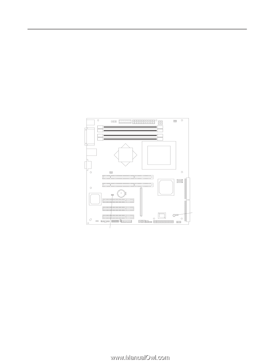
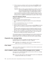
Recovering from a POST/BIOS update failure If power to the server is interrupted while POST/BIOS code is being updated (flash update), the server might not restart correctly or might not display video (no video). If this happens, complete the following steps to recover: 1. Review the safety information beginning at "Safety information" on page 107 and "Handling static-sensitive devices" on page 24. 2. Turn off the server and all attached devices. 3. Disconnect the power cord and all external cables. 4. Remove the side cover and support bracket (see "Removing the side cover" on page 26 and "Removing and installing the support bracket" on page 28). 5. Locate the boot block recovery jumper (JP1) on the system board, removing any adapters that impede access to the jumper. The following illustration shows the location of the jumper on the system board. Boot block jumper (JP1) CMOS jumper (JP2) 6. Remove the boot block recovery jumper from pins 1 and 2. 7. Replace any adapters that were removed; then, replace the support bracket and replace the side cover (see "Removing and installing the support bracket" on page 28 and "Replacing the side cover" on page 50). 8. Connect the server to a power source, keyboard, monitor, and mouse. 9. Insert the POST/BIOS update (flash) diskette into the diskette drive. You can download a file to create this diskette from http://www.ibm.com/pc/support/. 10. Turn on the server and the monitor. 11. After the update session is completed, turn off the server and monitor. 12. Remove the diskette from the diskette drive. 13. Disconnect all power cords and external cables; then, remove the server cover. 14. Return the boot block recovery jumper to pins 1 and 2. 15. Reinstall the server cover; then, reconnect all external cables and power cords and turn on the peripheral devices. 16. Turn on the server to restart the operating system. 20 xSeries 206 Type 8482 and 8487: Hardware Maintenance Manual and Troubleshooting Guide
-
 1
1 -
2
-
3
-
4
-
5
-
6
-
7
-
8
-
9
-
10
-
11
-
12
-
13
-
14
-
15
-
16
-
17
-
18
-
19
-
20
-
21
-
22
-
23
-
24
-
 25
25 -
 26
26 -
 27
27 -
 28
28 -
 29
29 -
 30
30 -
 31
31 -
 32
32 -
 33
33 -
 34
34 -
 35
35 -
36
-
37
-
38
-
39
-
40
-
41
-
42
-
43
-
44
-
45
-
46
-
47
-
48
-
49
-
50
-
51
-
52
-
53
-
54
-
55
-
56
-
57
-
58
-
59
-
60
-
61
-
62
-
63
-
64
-
65
-
66
-
67
-
68
-
69
-
70
-
71
-
72
-
73
-
74
-
75
-
76
-
77
-
78
-
79
-
80
-
81
-
82
-
83
-
84
-
85
-
86
-
87
-
88
-
89
-
90
-
91
-
92
-
93
-
94
-
95
-
96
-
97
-
98
-
99
-
100
-
101
-
102
-
103
-
104
-
105
-
106
-
107
-
108
-
109
-
110
-
111
-
112
-
113
-
114
-
115
-
116
-
117
-
118
-
119
-
120
-
121
-
122
-
123
-
124
-
125
-
126
-
127
-
128
-
129
-
130
-
131
-
132
-
133
-
134
-
135
-
136
-
137
-
138
-
139
-
140
-
141
-
142
-
143
-
144
-
145
-
146
-
147
-
148
-
149
-
150
-
151
-
152
-
153
-
154
-
155
-
156
-
157
-
158
-
159
-
160
 |
 |