IBM 8676M1X User Manual - Page 19
Server controls, LEDs, and power, Front view, USB 2 connector
 |
View all IBM 8676M1X manuals
Add to My Manuals
Save this manual to your list of manuals |
Page 19 highlights
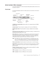
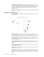
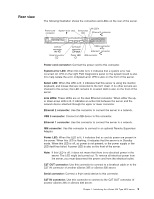
Server controls, LEDs, and power This section describes the controls and light-emitting diodes (LEDs) and how to turn the server on and off. Front view The following illustration shows the controls, LEDs, and connectors on the front of the server. CD-eject button CD-ROM drive activity LED Diskette-eject button Hard disk drive activity LEDs Power LED Diskette drive activity LED Hard disk drive status LEDs USB 1 connector USB 2 connector Operator information panel Power control button Reset button CD-ROM drive activity LED: When this LED is lit, it indicates that the CD-ROM drive is in use. CD-eject button: Press this button to release a CD from the CD-ROM drive. Diskette-eject button: Press this button to release a diskette from the diskette drive. Hard disk drive activity LEDs: When these LEDs are flashing, it indicates that the associated SCSI hard disk drive is in use. Power LED: When this LED is lit, it indicates that ac and dc power are present in the server. When this LED is flashing, it indicates that the server is in Standby mode. When this LED is off, ac power is not present, or the power supply or the LED itself has failed. A power LED is also on the rear of the server. Note: If this LED is off, it does not mean that there is no electrical power in the server. The LED might be burned out. To remove all electrical power from the server, you must disconnect the power cord from the electrical outlet. Power-control button: Press this button to turn the server on and off manually. Reset button: Press this button to reset the server and run the power-on self-test (POST). You might have to use a pen or the end of a straightened paper clip to press the button. Operator information panel: This panel contains controls and LEDs. For details, see "Operator information panel" on page 8. USB 2 connector: Connect a USB device to this connector. USB 1 connector: Connect a USB device to this connector. Chapter 1. Introducing the xSeries 335 Type 8676 server 7
-
 1
1 -
2
-
3
-
4
-
5
-
6
-
7
-
8
-
9
-
10
-
11
-
12
-
13
-
 14
14 -
 15
15 -
 16
16 -
 17
17 -
 18
18 -
 19
19 -
 20
20 -
 21
21 -
 22
22 -
 23
23 -
 24
24 -
25
-
26
-
27
-
28
-
29
-
30
-
31
-
32
-
33
-
34
-
35
-
36
-
37
-
38
-
39
-
40
-
41
-
42
-
43
-
44
-
45
-
46
-
47
-
48
-
49
-
50
-
51
-
52
-
53
-
54
-
55
-
56
-
57
-
58
-
59
-
60
-
61
-
62
-
63
-
64
 |
 |
