IBM VXA-2 User Guide - Page 14
Setting the SCSI ID and termination - tape drive
 |
View all IBM VXA-2 manuals
Add to My Manuals
Save this manual to your list of manuals |
Page 14 highlights
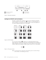
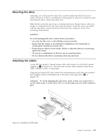
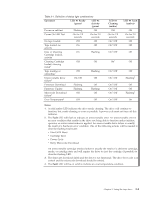
1 Term power connector 2 SCSI connector Figure 2-1. Back-panel components 3 SCSI ID jumpers 4 Power connector Setting the SCSI ID and termination The drive is shipped with a SCSI ID of 0. If you want to change the default ID, install the jumpers on the jumper block ( 3 in Figure 2-1) for the desired ID, as shown in Figure 2-2. (If necessary, use flat-nose pliers to remove the jumpers.) If you need an additional jumper, use a 2 mm jumper. Address 0 Address 1 Address 8 Address 9 Address 2 Address 3 Address 10 Address 11 Address 4 Address 5 Address 12 Address 13 Address 6 Address 7 Address 14 Address 15 Figure 2-2. SCSI ID settings You can use the connector ( 1 in Figure 2-1) to enable the terminator power signal. (The drive is shipped from the factory with termination power disabled.) To enable termination power, place a jumper across the far right pins on the auxiliary connector. Make sure the jumper is firmly in place. Be sure to use a 2 mm jumper. Figure 2-3. Term power enabled Note: To protect the drive components if termination power is shorted, the tape drive includes a self-resetting power fuse. 2-2 VXA-2 Internal Tape Drive: User's Guide
-
 1
1 -
2
-
3
-
4
-
5
-
6
-
7
-
8
-
 9
9 -
 10
10 -
 11
11 -
 12
12 -
 13
13 -
 14
14 -
 15
15 -
 16
16 -
 17
17 -
 18
18 -
 19
19 -
20
-
21
-
22
-
23
-
24
-
25
-
26
-
27
-
28
-
29
-
30
-
31
-
32
-
33
-
34
-
35
-
36
-
37
-
38
-
39
-
40
-
41
-
42
-
43
-
44
-
45
-
46
-
47
-
48
-
49
-
50
-
51
-
52
-
53
-
54
-
55
-
56
 |
 |
