IBM x3655 User Guide - Page 40
Removing, cover, riser-card, assembly
 |
UPC - 883436014533
View all IBM x3655 manuals
Add to My Manuals
Save this manual to your list of manuals |
Page 40 highlights
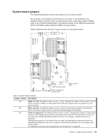
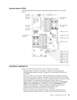
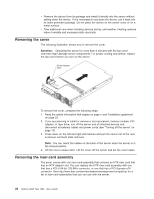
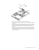
v Remove the device from its package and install it directly into the server without setting down the device. If it is necessary to set down the device, put it back into its static-protective package. Do not place the device on the server cover or on a metal surface. v Take additional care when handling devices during cold weather. Heating reduces indoor humidity and increases static electricity. Removing the cover The following illustration shows how to remove the cover. Attention: Operating the server for more than 2 minutes with the top cover removed might damage server components. For proper cooling and airflow, replace the top cover before you turn on the server. Cover-release latch To remove the cover, complete the following steps: 1. Read the safety information that begins on page v and "Installation guidelines" on page 23. 2. If you are planning to install or remove a microprocessor, memory module, PCI adapter, or tape drive, turn off the server and all attached devices and disconnect all external cables and power cords (see "Turning off the server" on page 13). 3. Press down on the left and right side latches and pull the server out of the rack enclosure until both slide rails lock. Note: You can reach the cables on the back of the server when the server is in the locked position. 4. Lift the cover-release latch. Lift the cover off the server and set the cover aside. Removing the riser-card assembly The sever comes with one riser-card assembly that contains an HTX riser card that has an HTX adapter slot. You can replace the HTX riser-card assembly with one that has a PCI-X 64-bit 133 MHz connector, or one that has a PCI-Express x16 connector. See http://www.ibm.com/servers/eserver/serverproven/compat/us/ for a list of riser-card assemblies that you can use with the server. 26 System x3655 Type 7985: User's Guide
-
 1
1 -
2
-
3
-
4
-
5
-
6
-
7
-
8
-
9
-
10
-
11
-
12
-
13
-
14
-
15
-
16
-
17
-
18
-
19
-
20
-
21
-
22
-
23
-
24
-
25
-
26
-
27
-
28
-
29
-
30
-
31
-
32
-
33
-
34
-
 35
35 -
 36
36 -
 37
37 -
 38
38 -
 39
39 -
 40
40 -
 41
41 -
 42
42 -
 43
43 -
 44
44 -
 45
45 -
46
-
47
-
48
-
49
-
50
-
51
-
52
-
53
-
54
-
55
-
56
-
57
-
58
-
59
-
60
-
61
-
62
-
63
-
64
-
65
-
66
-
67
-
68
-
69
-
70
-
71
-
72
-
73
-
74
-
75
-
76
-
77
-
78
-
79
-
80
-
81
-
82
-
83
-
84
-
85
-
86
-
87
-
88
-
89
-
90
-
91
-
92
-
93
-
94
-
95
-
96
-
97
-
98
-
99
-
100
-
101
-
102
-
103
-
104
-
105
-
106
-
107
-
108
-
109
-
110
-
111
-
112
-
113
-
114
-
115
-
116
-
117
-
118
 |
 |
