IC Realtime AVS-Z4212S Product Manual - Page 29
Cable Connection
 |
View all IC Realtime AVS-Z4212S manuals
Add to My Manuals
Save this manual to your list of manuals |
Page 29 highlights
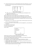
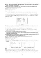
4 Cable Connection 4.1 Cable Connection The speed dome combination cable includes video cable connection port, RS485 connection port, alarm input and output port, and power cable connection port. Please refer to the label for detailed information. Slight difference may be found in the port amount since some functions are optional. Name Function A 485 B 485-A. It is to control dome built-in PTZ. 485-B. It is to control dome built-in PTZ. AC24V 24V power port. Connect to the power cable. EARTH Ground port. HD AVS BNC port. HD AVS standard signal to control the speed dome. Audio IN GND Input audio Audio GND port. Sheet 4-1 Relay in/out interfaces is shown below: Name Alarm out:1 Function One alarm output channel. When there is an alarm from current channel, system activates relay or not. Alarm output relay default setup is NO. You can use the jumpcap near the power board relay to set. NO:Normal open alarm output. Alarm out_com: 1 Alarm in:1-2 NC:Normal close alarm output. Alarm input ground end. Two alarm input channels. It is to receive relay signal from the external alarm source. You can go to dome menu to activate specified preset or patter. When the activation mode is NO (normal open), dome alarms when there is low voltage. High voltage will not activate the alarm. When the activation mode is NC (normal close), dome alarms when there is high voltage. Low voltage will not activate the alarm. Note: Dome alarm input message is ground mode. Dome alarm input signal are two modes: normal open and normal close. GND Alarm input ground end. 22
-
 1
1 -
2
-
3
-
4
-
5
-
6
-
7
-
8
-
9
-
10
-
11
-
12
-
13
-
14
-
15
-
16
-
17
-
18
-
19
-
20
-
21
-
22
-
23
-
 24
24 -
 25
25 -
 26
26 -
 27
27 -
 28
28 -
 29
29 -
 30
30 -
 31
31 -
 32
32 -
 33
33 -
 34
34 -
35
-
36
-
37
 |
 |
