IC Realtime AVS-Z4212S Product Manual - Page 30
System Layout
 |
View all IC Realtime AVS-Z4212S manuals
Add to My Manuals
Save this manual to your list of manuals |
Page 30 highlights
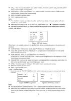
Sheet 4-2 4.2 System Layout 4.2.1 System Connection 4.2.1.1 BUS connection Please refer to Figure 4-1 for system connection information. Figure 4-1 Note: Please use shielded twisted pair. The shielded layer shall connect to GND firmly; otherwise it may affect communication or video work. 4.2.1.2 Star Connection Please refer to Figure 4-2 for alarm connection information. Figure 4-2 4.2.2 Alarm Connection Please refer to Figure 4-3 for alarm connection information. 23
-
 1
1 -
2
-
3
-
4
-
5
-
6
-
7
-
8
-
9
-
10
-
11
-
12
-
13
-
14
-
15
-
16
-
17
-
18
-
19
-
20
-
21
-
22
-
23
-
24
-
 25
25 -
 26
26 -
 27
27 -
 28
28 -
 29
29 -
 30
30 -
 31
31 -
 32
32 -
 33
33 -
 34
34 -
 35
35 -
36
-
37
 |
 |

23
Sheet 4-2
4.2 System Layout
4.2.1 System Connection
4.2.1.1 BUS connection
Please refer to Figure 4-1
for system connection information.
Figure 4-1
Note:
Please use shielded twisted pair. The shielded layer shall connect to GND firmly; otherwise it may affect
communication or video work.
4.2.1.2 Star Connection
Please refer to Figure 4-2 for alarm connection information.
Figure 4-2
4.2.2 Alarm Connection
Please refer to Figure 4-3 for alarm connection information.