Icom IC-M700PRO Instruction Manual - Page 19
Connector information
 |
View all Icom IC-M700PRO manuals
Add to My Manuals
Save this manual to your list of manuals |
Page 19 highlights
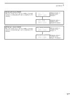
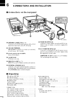
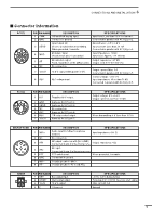
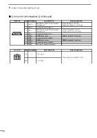
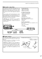
6 CONNECTIONS AND INSTALLATION ■ Connector information ACC(1) 4 25 1 3 8 6 7 PIN PIN NAME DESCRIPTION 1 CWK CW and FSK keying input. 2 GND Connects to ground. SPECIFICATIONS Input level: Less than 0.6 V for transmit. Connected in parallel with ACC(2) pin 2. 3 SEND Input/output pin. Goes to ground when transmitting. When grounded, transmits. Ground level: -0.5 to 0.8 V Input current: Less than 20 mA Connected in parallel with ACC(2) pin 3. 4 MOD Modulator input. Usable when pin 3 is grounded. Input impedance: 10 kø Input level: Approx. 100 mV rms 5 AF AF detector output. Output impedance: 4.7 kø Fixed, regardless of the [AF] position. Output level: 100-300 mV rms 6 NC No connection. 7 13.6 V 13.6 V output when power is ON. Output current: Max. 1 A Connected in parallel with ACC(2) pin 7. 8 ALC ALC voltage input. Control voltage: -3 to 0 V Input impedance: More than 10 kø Connected in parallel with ACC(2) pin 5. ACC(2) 4 25 1 3 6 7 PIN PIN NAME DESCRIPTION 1 8V Regulated 8 V output. 2 GND 3 SEND 4 NC 5 ALC 6 RLC 7 13.6 V Same as ACC(1) pin 2. Same as ACC(1) pin 3. No connection. Same as ACC(1) pin 8. T/R relay control output. Same as ACC(1) pin 7. SPECIFICATIONS Output voltage: 8 V ±0.3 V Output current: Less than 10 mA When transmitting: 0 V (less than 0.5 A) MICROPHONE 21 7 3 86 4 5 PIN PIN NAME DESCRIPTION SPECIFICATIONS 1 MIC+ Audio input from the microphone element. Input impedance: 600 ø 2 NC No connection. 3 AF1 AF output controlled with [VOLUME]. Connected to pin 4 in the microphone. Output impedance: 4 ø 4 AF2 AF input. Connected to pin 3 in the microphone. 5 PTT PTT switch input. When grounded, transmits. 6 GND Connected to ground. 7 MIC- Coaxial ground for MIC+. 8 AF- Coaxial ground for AF1 and AF2. TUNER 12 34 PIN PIN NAME DESCRIPTION 1 KEY Key signal input. 2 START Start signal output. 3 13.6V 13.6 V output 4E _ terminal SPECIFICATIONS -0.5 to 0.8 V during tuning Pulled up 8 V, 0 V(100 msec) as start signal. Max. current: 2 A Ground 16
-
 1
1 -
2
-
3
-
4
-
5
-
6
-
7
-
8
-
9
-
10
-
11
-
12
-
13
-
 14
14 -
 15
15 -
 16
16 -
 17
17 -
 18
18 -
 19
19 -
 20
20 -
 21
21 -
 22
22 -
 23
23 -
 24
24 -
25
-
26
-
27
-
28
 |
 |
