Icom IC-M700PRO Instruction Manual - Page 20
Connector information Continued
 |
View all Icom IC-M700PRO manuals
Add to My Manuals
Save this manual to your list of manuals |
Page 20 highlights
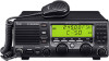
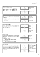
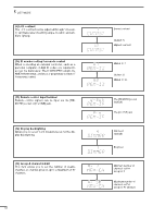
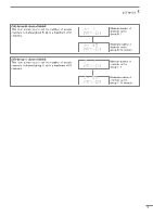
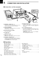
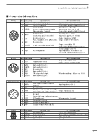
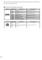
6 CONNECTIONS AND INSTALLATION ■ Connector information (Continued) REMOTE 6 9 1 5 PIN PIN NAME DESCRIPTION 1 MOD+ Modulation input from an external terminal unit. 2 MOD- Coaxial ground for MOD+. 3 AF+ AF detector output for an external terminal unit. 4 AF- Coaxial ground for AF+. 5 NMI+ NMEA data input. 6 NMI- Coaxial ground for NMI+. 7 NMO+ NMEA data output. 8 NMO- Coaxial ground for NMO+. 9 GND Ground for digital equipment. SPECIFICATIONS Input impedance: 600 ø Input level: Approx. 1.3 mV rms Output impedance: 600 ø Output level: 0.25-2.5 V rms NMEA standard format/level NMEA standard format/level DC 13.6V 123 456 PIN PIN NAME DESCRIPTION 1-3 + + DC input 4-6 - _ DC input SPECIFICATIONS Max. power consumption: 30 A 17
-
 1
1 -
2
-
3
-
4
-
5
-
6
-
7
-
8
-
9
-
10
-
11
-
12
-
13
-
14
-
 15
15 -
 16
16 -
 17
17 -
 18
18 -
 19
19 -
 20
20 -
 21
21 -
 22
22 -
 23
23 -
 24
24 -
 25
25 -
26
-
27
-
28
 |
 |

6
CONNECTIONS AND INSTALLATION
17
REMOTE
PIN
PIN NAME
DESCRIPTION
SPECIFICATIONS
2
MOD–
Coaxial ground for MOD+.
1
MOD+
Modulation input from an external
terminal unit.
Input impedance: 600
ø
Input level: Approx. 1.3 mV rms
4
AF–
Coaxial ground for AF+.
5
NMI+
NMEA data input.
NMEA standard format/level
6
NMI–
Coaxial ground for NMI+.
7
NMO+
NMEA data output.
NMEA standard format/level
3
AF+
AF detector output for an external
terminal unit.
Output impedance: 600
ø
Output level: 0.25–2.5 V rms
8
NMO–
Coaxial ground for NMO+.
9
GND
Ground for digital equipment.
6
9
5
1
DC 13.6V
PIN NAME
DESCRIPTION
SPECIFICATIONS
1–3
+
+
DC input
4–6
–
_
DC input
PIN
Max. power consumption: 30 A
1
2
4
6
3
5
■
Connector information (Continued)