Icom ID-1 Instruction Manual - Page 63
General
 |
View all Icom ID-1 manuals
Add to My Manuals
Save this manual to your list of manuals |
Page 63 highlights
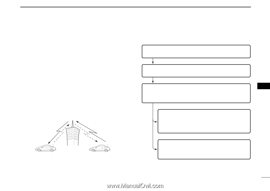
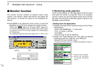
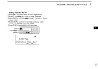
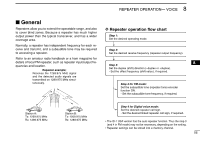
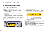
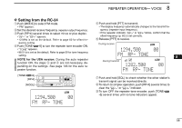
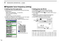
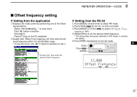
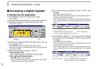
8 REPEATER OPERATION- VOICE General Repeaters allow you to extend the operatable range, and also to cover blind zones. Because a repeater has much higher output power than the typical transceiver, and has a wider coverage area. D Repeater operation flow chart Step 1: Set the desired operating mode. Normally, a repeater has independent frequency for each receive and transmit, and a subaudible tone may be required to accessing a repeater. Step 2: Set the desired receive frequency (repeater output frequency). Refer to an amateur radio handbook or a ham magazine for details of local FM repeater, such as repeater input/output fre- 8 quencies and location. Step 3: Set the duplex (shift) direction (-duplex or +duplex). Repeater example; Receives the 1269.975 MHz signal - Set the offset frequency (shift value), if required. and the detected audio signals are transmitted on 1289.975 MHz simul- taneously. Step 4 for FM mode: Set the subaudible tone (repeater tone) encoder function ON. - Set the subaudible tone frequency, if required. Station A: Tx: 1269.975 MHz Rx: 1289.975 MHz Station B: Tx: 1269.975 MHz Rx: 1289.975 MHz Step 4 for Digital voice mode: Set the desired repeater call sign. - Set the desired linked repeater call sign, if required. • The ID-1 USA version has the auto repeater function. Thus the step 3 (and 4 in FM mode) may not be necessary, depending on the setting. • Repeater settings can be stored into a memory channel. 56
-
 1
1 -
2
-
3
-
4
-
5
-
6
-
7
-
8
-
9
-
10
-
11
-
12
-
13
-
14
-
15
-
16
-
17
-
18
-
19
-
20
-
21
-
22
-
23
-
24
-
25
-
26
-
27
-
28
-
29
-
30
-
31
-
32
-
33
-
34
-
35
-
36
-
37
-
38
-
39
-
40
-
41
-
42
-
43
-
44
-
45
-
46
-
47
-
48
-
49
-
50
-
51
-
52
-
53
-
54
-
55
-
56
-
57
-
 58
58 -
 59
59 -
 60
60 -
 61
61 -
 62
62 -
 63
63 -
 64
64 -
 65
65 -
 66
66 -
 67
67 -
 68
68 -
69
-
70
-
71
-
72
-
73
-
74
-
75
-
76
-
77
-
78
-
79
-
80
-
81
-
82
-
83
-
84
-
85
-
86
-
87
-
88
-
89
-
90
-
91
-
92
-
93
-
94
-
95
-
96
-
97
-
98
-
99
-
100
-
101
-
102
-
103
-
104
-
105
-
106
-
107
-
108
-
109
-
110
-
111
-
112
-
113
-
114
-
115
-
116
-
117
-
118
-
119
-
120
-
121
-
122
-
123
-
124
 |
 |