Image Fitness 3.0 Bench English Manual - Page 6
Assembly
 |
View all Image Fitness 3.0 Bench manuals
Add to My Manuals
Save this manual to your list of manuals |
Page 6 highlights
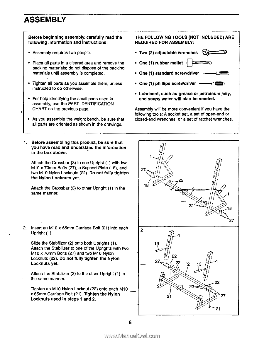
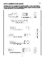
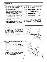
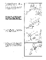
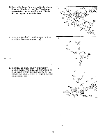
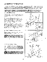
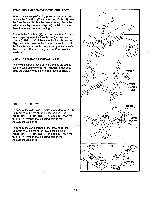
ASSEMBLY Before beginning assembly, carefully read the following information and instructions: • Assembly requires two people. • Place all parts in a cleared area and remove the packing materials; do not dispose of the packing materials until assembly is completed. • Tighten all parts as you assemble them, unless instructed to do otherwise. • For help identifying the small parts used in assembly, use the PART IDENTIFICATION CHART on the previous page. • As you assemble the weight bench, be sure that all parts are oriented as shown in the drawings. THE FOLLOWING TOOLS (NOT INCLUDED) ARE REQUIRED FOR ASSEMBLY: • Two (2) adjustable wrenches • One (1) rubber mallet • One (1) standard screwdriver • One (1) phillips screwdriver • Lubricant, such as grease or petroleum jelly, and soapy water will also be needed. Assembly will be more convenient if you have the following tools: A socket set, a set of open-end or closed-end wrenches, or a set of ratchet wrenches. 1. Before assembling this product, be sure that you have read and understand the information - In the box above. 1 Attach the Crossbar (3) to one Upright (1) with two M10 x 70mm Bolts (27), a Support Plate (18), and two M10 Nylon Locknuts (22). Do not fully tighten 27 the Nylen Lecknuta yat 22 Attach the Crossbar (3) to other Upright (1) in the 18 same manner. 22 18 27 2. Insert an M10 x 65mm Carriage Bolt (21) into each Upright (1). 2 Slide the Stabilizer (2) onto both Uprights (1). Attach the Stabilizer to one of the Uprights with two M10 x 70mm Bolts (27) anct tWO M10 Nylon Locknuts (22). Do not fully tighten the Nylon Locknuts yet. Attach the Stabilizer (2) to the other Upright (1) in the same manner. Tighten an M10 Nylon Locknut (22) onto each M10 x 65mm Carriage Bolt (21). Tighten the Nylon Locknuts used in steps 1 and 2. 13 22 27 22 2 13 4 22 22 21 • 27 21 6
-
 1
1 -
 2
2 -
 3
3 -
 4
4 -
 5
5 -
 6
6 -
 7
7 -
 8
8 -
 9
9 -
 10
10 -
 11
11 -
 12
12 -
13
-
14
-
15
-
16
-
17
-
18
-
19
 |
 |