Intel AXXRSBBU4 User Guide - Page 7
Installing the AXXRSBBU4, Top and Bottom View of the AXXRSBBU4
 |
View all Intel AXXRSBBU4 manuals
Add to My Manuals
Save this manual to your list of manuals |
Page 7 highlights
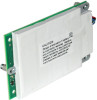
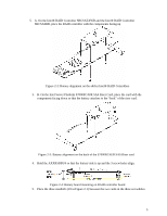
Installing the AXXRSBBU4 Figure 2.1 displays the top and bottom views of the AXXRSBBU4. The battery pack is mounted on a daughtercard which mounts to the RAID controller. Take note of the location of the J2 connector (5) which plugs into the Intel® RAID Controller and the 3 standoffs (2)and 6 screws (3). Only the top side of the daughtercard will be visible after installation onto the RAID controller. Figure 2-1: Top and Bottom View of the AXXRSBBU4 3
-
 1
1 -
 2
2 -
 3
3 -
 4
4 -
 5
5 -
 6
6 -
 7
7 -
 8
8 -
 9
9 -
 10
10 -
 11
11 -
 12
12 -
13
-
14
 |
 |

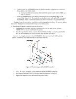
Installing the AXXRSBBU4
Figure 2.1 displays the top and bottom views of the AXXRSBBU4. The battery pack is mounted on
a daughtercard which mounts to the RAID controller. Take note of the location of the J2 connector
(5) which plugs into the Intel® RAID Controller and the 3 standoffs (2)and 6 screws (3). Only the
top side of the daughtercard will be visible after installation onto the RAID controller.
Figure 2-1: Top and Bottom View of the AXXRSBBU4
3