Intel BLKDP55WG Product Specification
Intel BLKDP55WG - P55 LG1156 MAX-16 GB DDR3 ATX Motherboard Manual
 |
UPC - 735858206044
View all Intel BLKDP55WG manuals
Add to My Manuals
Save this manual to your list of manuals |
Intel BLKDP55WG manual content summary:
- Intel BLKDP55WG | Product Specification - Page 1
® Desktop Board DP55WG Technical Product Specification September 2009 Order Number: E70715-001US The Intel® Desktop Board DP55WG may contain design defects or errors known as errata that may cause the product to deviate from published specifications. Current characterized errata are documented in - Intel BLKDP55WG | Product Specification - Page 2
Intel may make changes to specifications and product descriptions at any time, without notice. Designers must not rely on the absence or characteristics of any features or instructions marked "reserved" or "undefined." Intel 9333. Intel, Core i7, and Core i5 are trademarks of Intel Corporation or its - Intel BLKDP55WG | Product Specification - Page 3
of information. It is specifically not intended for general audiences. What This Document Contains Chapter 1 2 3 4 5 Description A description of the hardware used on the Intel Desktop Board DP55WG A map of the resources of the Intel Desktop Board The features supported by the BIOS Setup program - Intel BLKDP55WG | Product Specification - Page 4
Intel Desktop Board DP55WG Technical Product Specification Other Common Notation # GB GB/s Gb/s KB Kbit kbits/s MB MB/s Mbit Mbits/s xxh x.x V * Used after a signal name to identify an active-low signal (such - Intel BLKDP55WG | Product Specification - Page 5
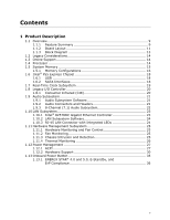
Feature Summary 9 1.1.2 Board Layout 11 1.1.3 Block Diagram 13 1.2 Legacy Considerations 14 1.3 Online Support 14 1.4 Processor 14 1.5 System Memory 15 1.5.1 Memory Configurations 16 1.6 Intel® P55 Express Chipset 18 1.6.1 USB 18 1.6.2 SATA Interfaces 18 1.7 Real-Time Clock Subsystem 19 - Intel BLKDP55WG | Product Specification - Page 6
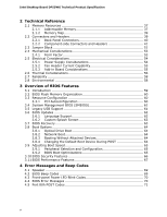
Intel Desktop Board DP55WG Technical Product Specification 2 Technical Reference 2.1 Memory Resources 37 2.1.1 Addressable Memory 37 2.1.2 System Management BIOS (SMBIOS 61 3.5 Legacy USB Support 61 3.6 BIOS Updates 62 3.6.1 Language Support 62 3.6.2 Custom Splash Screen 63 3.7 BIOS Recovery - Intel BLKDP55WG | Product Specification - Page 7
57 Tables 1. Feature Summary 9 2. Components Shown in Figure 1 12 3. Supported Memory Configurations 15 4. LAN Connector LED States 24 5. Effects of Pressing the . Chassis Intrusion Header 44 15. Processor, Front and Rear Chassis (4-Pin) Fan Headers 44 16. Processor Core Power Connector 46 vii - Intel BLKDP55WG | Product Specification - Page 8
Intel Desktop Board DP55WG Technical Product Specification 17. Main Power Connector 47 18. Front Panel Header 48 Fan Header Current Capability 55 24. Thermal Considerations for Components 57 25. Environmental Specifications 58 26. BIOS Setup Program Menu Bar 60 27. BIOS Setup Program Function - Intel BLKDP55WG | Product Specification - Page 9
™ i5 and Intel® Core™ i5 processors in an LGA1156 socket: ― 1 x16 PCIe 2.0 Graphics interface (operates in x8 mode when second slot is populated) ― 1 x8 PCIe 2.0 Graphics interface ― Two DDR3 memory channels • Four 240-pin DDR3 SDRAM Dual Inline Memory Module (DIMM) sockets • Support for DDR3 1600 - Intel BLKDP55WG | Product Specification - Page 10
Product Specification Table 1. Feature Summary (continued) LAN Support Gigabit (10/100/1000 Mbits/s) LAN subsystem using the Intel® 82578DC for 4-pin fan headers (processor and front and rear chassis) with selectable support in BIOS for 3 wire fans • Support for Platform Environmental Control - Intel BLKDP55WG | Product Specification - Page 11
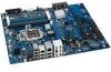
Product Description 1.1.2 Board Layout Figure 1 shows the location of the major components on Intel Desktop Board DP55WG. Figure 1. Major Board Components Table 2 lists the components identified in Figure 1. 11 - Intel BLKDP55WG | Product Specification - Page 12
Intel Desktop Board DP55WG Technical Product Specification Table processor core voltage connector (2 x 4) N Processor fan header O Processor LED (red) P Voltage regulator LED (red) Q Processor headers (2) EE IEEE 1394a header FF Intel P55 Express Chipset GG BIOS configuration jumper - Intel BLKDP55WG | Product Specification - Page 13
Product Description 1.1.3 Block Diagram Figure 2 is a block diagram of the major functional areas of the board. Figure 2. Block Diagram 13 - Intel BLKDP55WG | Product Specification - Page 14
http://downloadcenter.intel.com http://support.intel.com/support/motherboards/desktop/sb/CS025414.htm http://www.intel.com/support/go/buildit 1.4 Processor The board is designed to support the Intel Core i7 and Intel Core i5 processors in an LGA1156 socket Other processors may be supported in the - Intel BLKDP55WG | Product Specification - Page 15
compliant with all applicable DDR SDRAM memory specifications, the board should be populated with DIMMs that support the Serial Presence Detect (SPD) data Refer to: http://support.intel.com/support/motherboards/desktop/sb/CS025414.htm http://www.intel.com/personal/gaming/extremememory.htm 15 - Intel BLKDP55WG | Product Specification - Page 16
Desktop Board DP55WG Technical Product Specification 1.5.1 Memory Configurations The Intel Core i7 and Intel Core i5 processors supports the following types of memory organization: ... Memory Configuration Examples Refer to: http://www.intel.com/support/motherboards/desktop/sb/cs011965.htm 16 - Intel BLKDP55WG | Product Specification - Page 17
Product Description Figure 3 illustrates the memory channel and DIMM configuration. Figure 3. Memory Channel and DIMM Configuration NOTE For the system to boot, always install memory into the blue DIMM memory slots if only installing two DIMMs in your configuration. 17 - Intel BLKDP55WG | Product Specification - Page 18
Desktop Board DP55WG Technical Product Specification 1.6 Intel® P55 Express Chipset The Intel P55 Express Chipset consisting of the Intel P55 Express Platform Controller Hub (PCH) provides interfaces to the processor and the USB, SATA, LPC, LAN, PCI, and PCIe interfaces. The PCH is a centralized - Intel BLKDP55WG | Product Specification - Page 19
SATA connectors (black) from the PCH. NOTE In order to use supported RAID features, you must first enable RAID in the BIOS. Also, during Microsoft Windows XP installation, you must press F6 to install the RAID drivers. See your Microsoft Windows XP documentation for more information about installing - Intel BLKDP55WG | Product Specification - Page 20
Intel Desktop Board DP55WG Technical Product Specification 1.8 Legacy I/O Controller The I/O controller provides the following features: • Consumer Infrared (CIR) headers • Serial IRQ interface compatible with serialized IRQ support for PCI systems • Intelligent power management, including a - Intel BLKDP55WG | Product Specification - Page 21
board supports the Intel High Definition Audio subsystem based on the Realtek ALC889 audio codec. The audio subsystem supports the following Audio software and drivers are available from Intel's World Wide Web site. For information about Obtaining audio software and drivers Refer to Section - Intel BLKDP55WG | Product Specification - Page 22
Desktop Board DP55WG Technical Product Specification 1.9.3 8-Channel (7.1) Audio Subsystem The 8-channel (7.1) audio subsystem includes the following: • Intel P55 PCH • Realtek ALC889 audio codec • Microphone input that supports a single dynamic, condenser, or electret microphone The back panel - Intel BLKDP55WG | Product Specification - Page 23
capabilities • LAN subsystem software For information about LAN software and drivers Refer to http://downloadcenter.intel.com 1.10.1 Intel® 82578DC Gigabit Ethernet Controller The Intel 82578DC Gigabit Ethernet Controller supports the following features: • 10/100/1000 BASE-T IEEE 802.3 compliant - Intel BLKDP55WG | Product Specification - Page 24
Desktop Board DP55WG Technical Product Specification 1.10.2 LAN Subsystem Software LAN software and drivers are available from Intel's World Wide Web site. For information about Obtaining LAN software and drivers Refer to http://downloadcenter.intel.com 1.10.3 RJ-45 LAN Connector with Integrated - Intel BLKDP55WG | Product Specification - Page 25
Management (WfM) specification. The board Control ASIC • Thermal sensors in the processor and PCH • Power supply monitoring of Monitoring Fan monitoring can be implemented using Intel® Desktop Control Center or third-party Intrusion and Detection The board supports a chassis security feature that - Intel BLKDP55WG | Product Specification - Page 26
Product Specification 1.11.4 Thermal Monitoring Figure 6 shows the locations of the thermal sensors and fan headers. Item A B C D E F Description Rear chassis fan header Processor fan header Thermal diode, located on processor die Front chassis fan header Thermal diode, located on the Intel P55 - Intel BLKDP55WG | Product Specification - Page 27
of ACPI with this board requires an operating system that provides full ACPI support. ACPI features include: • Plug and Play (including bus and device , add-in boards (some add-in boards may require an ACPI-aware driver), video displays, and hard disk drives • Methods for achieving less than - Intel BLKDP55WG | Product Specification - Page 28
Intel Desktop Board DP55WG Technical Product Specification supported by the board along with the associated system power targets. See the ACPI specification state S1 - Processor stopped C1 - stop grant D1, D2, D3 - device specification specific. 5 W to the system. Service can be performed safely - Intel BLKDP55WG | Product Specification - Page 29
events that can wake the computer from specific states. Table 7. Wake-up Devices and Events These devices/events can wake up the computer... Power switch RTC alarm LAN USB PME# signal WAKE# Consumer IR Notes: 1. S4 implies operating system support only. 2. Wake from S4 and S5 is recommended - Intel BLKDP55WG | Product Specification - Page 30
Intel Desktop Board DP55WG Technical Product Specification 1.12.2 Hardware Support CAUTION Ensure that the power supply from USB from an ACPI state requires an operating system that provides full ACPI support. 1.12.2.1 Power Connector ATX12V-compliant power supplies can turn off the system power - Intel BLKDP55WG | Product Specification - Page 31
input of the hardware monitoring and fan control ASIC • All fan headers support closed-loop fan control that can adjust the fan speed or switch the fan powers up the computer. Depending on the LAN implementation, the board supports LAN wake capabilities with ACPI in the following ways: • The PCI - Intel BLKDP55WG | Product Specification - Page 32
-in boards that also support this specification can participate in power management and can be used to wake the computer. The use of Instantly Available PC technology requires operating system support and PCI 2.2 compliant add-in cards, PCI Express add-in cards, and drivers. 1.12.2.5 Wake from USB - Intel BLKDP55WG | Product Specification - Page 33
and any attached devices. In addition to the standby power indicator, the board contains three LEDs that indicate the following: • The processor LED indicates an elevated temperature on the processor that could effect performance • The Voltage Regulator LED indicates an elevated temperature in the - Intel BLKDP55WG | Product Specification - Page 34
Intel Desktop Board DP55WG Technical Product Specification Figure 7 shows the location of these additional LEDs. Item A B C D Description Processor LED (red) Voltage regulator LED (red) Standby power indicator LED (green) SATA drive activity LED (blue) Figure 7. Locations of Indicator LEDs 34 - Intel BLKDP55WG | Product Specification - Page 35
Product Description 1.13 Onboard Power Button The board provides a power button that can be used to turn the computer on or off. This button is intended for use at integration facilities to provide the ability to power on/off the board without the need to attach a front panel switch (the onboard - Intel BLKDP55WG | Product Specification - Page 36
Desktop Board DP55WG Technical Product Specification 1.13.1 ENERGY STAR* 4.0 and 5.0, E-Standby, and ErP Compliance The US Department of Energy and the US Environmental Protection Agency have continually revised the ENERGY STAR requirements. Intel has worked directly with these two governmental - Intel BLKDP55WG | Product Specification - Page 37
2 Technical Reference 2.1 Memory Resources 2.1.1 Addressable Memory The board utilizes 16 GB of addressable system memory. Typically the address space that is allocated for PCI Conventional bus add-in cards, PCI Express configuration space, BIOS (SPI Flash device), and chipset overhead resides above - Intel BLKDP55WG | Product Specification - Page 38
Intel Desktop Board DP55WG Technical Product Specification Figure 9. Detailed System Memory Address Map 38 - Intel BLKDP55WG | Product Specification - Page 39
Technical Reference 2.1.2 Memory Map Table 8 lists the system memory map. Table 8. System Memory Map Address Range (decimal) Address Range (hex) 1024 K - 16777216 K 100000 - 3FFFFFFFF 960 K - 1024 K F0000 - FFFFF 896 K - 960 K E0000 - EFFFF 800 K - 896 K C8000 - DFFFF 640 K - 800 K 639 K - Intel BLKDP55WG | Product Specification - Page 40
Intel Desktop Board DP55WG Technical Product Specification 2.2.1 Back Panel Connectors Figure 10 shows the location of the back panel connectors for the board. Item A B C D E F G H I J K L M N Description Back-to-BIOS button S/PDIF in (optical) S/ - Intel BLKDP55WG | Product Specification - Page 41
Technical Reference 2.2.2 Component-side Connectors and Headers Figure 11 shows the locations of the component-side connectors and headers. Figure 11. Component-side Connectors and Headers Table 9 lists the component-side connectors and headers identified in Figure 11. 41 - Intel BLKDP55WG | Product Specification - Page 42
Intel Desktop Board DP55WG Technical Product Specification Table 9. Component-side Connectors and Headers Shown in Figure 11 Item/callout from Figure x1 connector PCI Express 2.0 x16 connector 12 V processor core voltage connector (2 x 4) Processor fan header Main power connector (2 x 12) Front - Intel BLKDP55WG | Product Specification - Page 43
Technical Reference 2.2.2.1 Signal Tables for the Connectors and Headers Table 10. IEEE 1394a Header Pin Signal Name 1 Data A (positive) 3 Ground 5 Data B (positive) 7 +12 V DC 9 Key (no pin) Pin 2 4 6 8 10 Signal Name Data A (negative) Ground Data B (negative) +12 V DC Ground Table - Intel BLKDP55WG | Product Specification - Page 44
Intel Desktop Board DP55WG Technical Product Specification Table 14. Chassis Intrusion Header Pin Signal Name 1 Intruder# 2 Ground Table 15. Processor, Front and Rear Chassis (4-Pin) Fan Headers Pin Signal Name 1 Ground (Note) 2 +12 V 3 FAN_TACH 4 FAN_CONTROL Note: These fan - Intel BLKDP55WG | Product Specification - Page 45
. • SMBus signals are routed to the PCI Conventional bus connectors. This enables PCI Conventional bus add-in boards with SMBus support to access sensor data on the desktop board. The specific SMBus signals are as follows: ⎯ The SMBus clock line is connected to pin A40. ⎯ The SMBus data line is - Intel BLKDP55WG | Product Specification - Page 46
Board DP55WG Technical Product Specification 2.2.2.3 Power Supply Connectors The board has the following power supply connectors: • Main power - a 2 x 12 connector. This connector is compatible with 2 x 10 connectors previously used on Intel Desktop boards. The board supports the use of ATX12V - Intel BLKDP55WG | Product Specification - Page 47
Technical Reference Table 17. Main Power Connector Pin Signal Name 1 +3.3 V 2 +3.3 V 3 Ground Pin Signal Name 13 +3.3 V 14 -12 V 15 Ground 4 +5 V 5 Ground 6 +5 V 7 Ground 16 PS-ON# (power supply remote on/off) 17 Ground 18 Ground 19 Ground 8 PWRGD (Power Good) 9 +5 - Intel BLKDP55WG | Product Specification - Page 48
Intel Desktop Board DP55WG Technical Product Specification 2.2.2.4 Front Panel Header This section describes the functions of the front panel header. Table 18 lists the signal names of the front panel header. Figure - Intel BLKDP55WG | Product Specification - Page 49
Running Steady Yellow Sleeping NOTE The colors listed in Table 19 and Table 20 are suggested colors only. Actual LED colors are chassis-specific. 2.2.2.4.4 Power Switch Header Pins 6 and 8 can be connected to a front panel momentary-contact power switch. The switch must pull the SW_ON# pin to - Intel BLKDP55WG | Product Specification - Page 50
Intel Desktop Board DP55WG Technical Product Specification 2.2.2.5 Front Panel USB Headers Figure 13 is a connection diagram for the front panel USB headers. NOTE • The +5 V DC power on the USB headers is fused. • Use only a front panel USB connector that conforms to the USB 2.0 specification for - Intel BLKDP55WG | Product Specification - Page 51
the three modes: normal, configure, and recovery. When the jumper is set to configure mode and the computer is powered-up, the BIOS compares the processor version and the microcode version in the BIOS and reports if the two match. Figure 15. Location of the Jumper Block 51 - Intel BLKDP55WG | Product Specification - Page 52
Intel Desktop Board DP55WG Technical Product Specification Table 21. BIOS Setup Configuration Jumper Settings Function/Mode Normal Jumper Setting 1-2 Configuration The BIOS uses current configuration information and passwords for booting. Configure 2-3 Recovery - Intel BLKDP55WG | Product Specification - Page 53
.00 inches by 9.60 inches [304.80 millimeters by 243.84 millimeters]. Location of the I/O connectors and mounting holes are in compliance with the ATX specification. Figure 16. Board Dimensions 53 - Intel BLKDP55WG | Product Specification - Page 54
of the ATX form factor specification. • The potential relation between 3.3 V DC and +5 V DC power rails • The current capability of the +5 VSB line • All timing parameters • All voltage tolerances For example, for a system consisting of a supported 95 W processor (see Section 1.4 on page 14 - Intel BLKDP55WG | Product Specification - Page 55
Table 23 lists the current capability of the fan headers. Table 23. Fan Header Current Capability Fan Header Maximum Available Current Processor fan Front chassis fan Rear chassis fan 1.5 A 1.0 A 1.0 A 2.5.3 Add-in Board Considerations The board is designed to provide 2 A (average) of current - Intel BLKDP55WG | Product Specification - Page 56
remains solely with the reader. Intel makes no warranties or representations that merely following the instructions presented in this document will , see the environmental specifications in Section 2.8. CAUTION Ensure that proper airflow is maintained in the processor voltage regulator circuit. - Intel BLKDP55WG | Product Specification - Page 57
Components Component Maximum Case Temperature Processor For processor case temperature, see processor datasheets and processor specification updates Intel P55 Express Chipset 111 oC (under bias) For information about Processor datasheets and specification updates Refer to Section 1.3, page - Intel BLKDP55WG | Product Specification - Page 58
Intel Desktop Board DP55WG Technical Product Specification 2.7 Reliability The Mean Time Between Failures (MTBF) prediction is calculated using component and subassembly random failure rates. The calculation is based on the Bellcore Reliability - Intel BLKDP55WG | Product Specification - Page 59
The board uses an Intel BIOS that is stored in the Serial Peripheral Interface Flash Memory (SPI Flash) and can be updated using a disk-based program. The SPI Flash contains the BIOS Setup program, POST, the PCI auto-configuration utility, LAN EEPROM information, and Plug and Play support. The BIOS - Intel BLKDP55WG | Product Specification - Page 60
Intel Desktop Board DP55WG Technical Product Specification Table 26 lists the BIOS Setup program menu features. Table 26. BIOS Setup Program Menu Bar Maintenance Main Advanced Performance Security Clears passwords and displays processor information Displays processor and memory configuration - Intel BLKDP55WG | Product Specification - Page 61
size, cache size, and processor speed • Dynamic data, supports an SMBIOS table interface for such operating systems. Using this support, an SMBIOS service Support Legacy USB support enables USB devices to be used even when the operating system's USB drivers are not yet available. Legacy USB support - Intel BLKDP55WG | Product Specification - Page 62
to prevent accidentally installing an incompatible BIOS. NOTE Review the instructions distributed with the upgrade utility before attempting a BIOS update. For information about BIOS update utilities Refer to http://support.intel.com/support/motherboards/desktop/sb /CS-022312.htm. 3.6.1 Language - Intel BLKDP55WG | Product Specification - Page 63
No Legacy diskette drive (with a 1.44 MB diskette) connected to the No legacy diskette drive interface For information about BIOS recovery Refer to http://www.intel.com/support/motherboards/desktop/sb/ cs-023360.htm 63 - Intel BLKDP55WG | Product Specification - Page 64
Intel Desktop Board DP55WG Technical Product Specification 3.8 Boot Options In the BIOS Setup program, the . 3.8.1 Optical Drive Boot Booting from the optical drive is supported in compliance to the El Torito bootable CD-ROM format specification. Under the Boot menu in the BIOS Setup program, the - Intel BLKDP55WG | Product Specification - Page 65
installed in it during POST. NOTE It is possible to optimize the boot process to the point where the system boots so quickly that the Intel logo screen (or a custom logo splash screen) will not be seen. Monitors and hard disk drives with minimum initialization times can also contribute to a boot - Intel BLKDP55WG | Product Specification - Page 66
Intel Desktop Board DP55WG Technical Product Specification 3.10 BIOS Security Features The BIOS includes security features that restrict access to the BIOS Setup program and who can boot the computer. A supervisor password - Intel BLKDP55WG | Product Specification - Page 67
The BIOS includes the following options to provide custom performance enhancements when using an Intel Core i7 and Intel Core i5 processors in an LGA 1156 socket. • Processor frequency adjustment • Processor voltage adjustment • Memory clock adjustments • Memory voltage adjustments • QPI Bus voltage - Intel BLKDP55WG | Product Specification - Page 68
Intel Desktop Board DP55WG Technical Product Specification 68 - Intel BLKDP55WG | Product Specification - Page 69
1, page 11 4.2 BIOS Beep Codes Whenever a recoverable error occurs during POST, the BIOS causes the board's speaker to beep an error message describing the problem (see Table 31). Table 31. BIOS Beep Codes Type Pattern F2 Setup/F10 Boot Menu One 0.5 second beep when BIOS is ready to Prompt - Intel BLKDP55WG | Product Specification - Page 70
Intel Desktop Board DP55WG Technical Product Specification 4.3 Front-panel Power LED Blink Codes Whenever a recoverable error occurs during POST, the BIOS causes the board's front panel power LED to blink an error message describing the problem (see Table 32). Table 32. Front-panel Power LED - Intel BLKDP55WG | Product Specification - Page 71
. Table 34. Port 80h POST Code Ranges Range Category/Subsystem 00 - 0F Debug codes: Can be used by any PEIM/driver for debug. 10 - 1F Host Processors: 1F is an unrecoverable CPU error. 20 - 2F Memory/Chipset: 2F is no memory detected or no useful memory detected. 30 - 3F Recovery: 3F - Intel BLKDP55WG | Product Specification - Page 72
Intel Desktop Board DP55WG Technical Product Specification Table 35. Port 80h POST Codes POST Code Description of POST Operation Host Processor 10 Power-on initialization of the host processor (Boot Strap Processor) 11 Host processor cache initialization (including APs) 12 Starting - Intel BLKDP55WG | Product Specification - Page 73
keyboard 93 Enabling the keyboard 94 Clearing keyboard input buffer 95 Instructing keyboard controller to run Self Test (PS/2 only) Mouse ( media BDS Dy Trying boot selection y (y=0 to 15) PEI Core E0 Started dispatching PEIMs (emitted on first report of EFI_SW_PC_INIT_BEGIN - Intel BLKDP55WG | Product Specification - Page 74
Intel Desktop Board DP55WG Technical Product Specification Table 35. Port 80h POST Codes (continued) POST Code Description of POST Operation DXE Drivers service ExitBootServices ( ) has been called F9 EFI runtime service SetVirtualAddressMap ( ) has been called FA EFI runtime service - Intel BLKDP55WG | Product Specification - Page 75
presence of memory DIMMs 25 Configuring memory 28 Testing memory 34 Loading recovery capsule E4 Entered DXE phase 12 Starting application processor initialization 13 SMM initialization 50 Enumerating PCI busses 51 Allocating resourced to PCI bus 92 Detecting the presence of the - Intel BLKDP55WG | Product Specification - Page 76
Intel Desktop Board DP55WG Technical Product Specification 76 - Intel BLKDP55WG | Product Specification - Page 77
Union Declaration of Conformity statement • Product Ecology statements • Electromagnetic Compatibility (EMC) standards • Product certification markings 5.1.1 Safety Standards Intel Desktop Board DP55WG complies with the safety standards stated in Table 37 when correctly installed in a compatible - Intel BLKDP55WG | Product Specification - Page 78
Desktop Board DP55WG Technical Product Specification 5.1.2 European Union Declaration of Conformity Statement We, Intel Corporation, declare under our sole responsibility that the product Intel® Desktop Board DP55WG is in conformity with all applicable essential requirements necessary for CE - Intel BLKDP55WG | Product Specification - Page 79
of this program, including the scope of covered products, available locations, shipping instructions, terms and conditions, etc Intel Product Recycling Program http://www.intel.com/intel/other/ehs/product_ecology Deutsch Als Teil von Intels Engagement für den Umweltschutz hat das Unternehmen das - Intel BLKDP55WG | Product Specification - Page 80
Specification Español Como parte de su compromiso de responsabilidad medioambiental, Intel ha implantado el programa de reciclaje de productos Intel, que permite que los consumidores al detalle de los productos Intel les instructions d'expédition, les conditions générales, etc http://www.intel.com/ - Intel BLKDP55WG | Product Specification - Page 81
Directive 2002/95/EC) compliant product. EU RoHS restricts the use of six materials. One of the six restricted materials is lead. This Intel Desktop Board is lead free although certain discrete components used on the board contain a small amount of lead which is necessary for component performance - Intel BLKDP55WG | Product Specification - Page 82
Intel Desktop Board DP55WG Technical Product Specification Table 38. Lead-Free Board Markings Description Lead-Free 2nd Level Interconnect: This symbol is used to identify electrical and electronic assemblies and components in - Intel BLKDP55WG | Product Specification - Page 83
Regulatory Compliance and Battery Disposal Information 5.1.4 EMC Regulations Intel Desktop Board DP55WG complies with the EMC regulations stated in Table 39 when correctly domestic environment, it may cause radio interference. Install and use the equipment according to the instruction manual. 83 - Intel BLKDP55WG | Product Specification - Page 84
Product Specification Korean Class B statement translation: this is household equipment that is certified to comply with EMC requirements. You may use this equipment in residential environments and other non-residential environments. 5.1.5 Product Certification Markings (Board Level) Intel Desktop - Intel BLKDP55WG | Product Specification - Page 85
Regulatory Compliance and Battery Disposal Information 5.2 Battery Disposal Information CAUTION Risk of explosion if the battery is replaced with an incorrect type. Batteries should be recycled where possible. Disposal of used batteries must be in accordance with local environmental regulations. - Intel BLKDP55WG | Product Specification - Page 86
Intel Desktop Board DP55WG Technical Product Specification PRECAUCIÓN Existe peligro de explosión si la pila no se cambia de forma adecuada. Utilice solamente pilas iguales o del mismo tipo que las recomendadas por - Intel BLKDP55WG | Product Specification - Page 87
Regulatory Compliance and Battery Disposal Information AWAS Risiko letupan wujud jika bateri digantikan dengan jenis yang tidak betul. Bateri sepatutnya dikitar semula jika boleh. Pelupusan bateri terpakai mestilah mematuhi peraturan alam sekitar tempatan. OSTRZEŻENIE Istnieje niebezpieczeństwo - Intel BLKDP55WG | Product Specification - Page 88
Intel Desktop Board DP55WG Technical Product Specification 88
-
 1
1 -
 2
2 -
 3
3 -
 4
4 -
 5
5 -
 6
6 -
 7
7 -
8
-
9
-
10
-
11
-
12
-
13
-
14
-
15
-
16
-
17
-
18
-
19
-
20
-
21
-
22
-
23
-
24
-
25
-
26
-
27
-
28
-
29
-
30
-
31
-
32
-
33
-
34
-
35
-
36
-
37
-
38
-
39
-
40
-
41
-
42
-
43
-
44
-
45
-
46
-
47
-
48
-
49
-
50
-
51
-
52
-
53
-
54
-
55
-
56
-
57
-
58
-
59
-
60
-
61
-
62
-
63
-
64
-
65
-
66
-
67
-
68
-
69
-
70
-
71
-
72
-
73
-
74
-
75
-
76
-
77
-
78
-
79
-
80
-
81
-
82
-
83
-
84
-
85
-
86
-
87
-
88
 |
 |

Intel® Desktop Board
DP55WG
Technical Product Specification
September 2009
Order Number:
E70715-001US
The Intel
®
Desktop Board DP55WG may contain design defects or errors known as errata that may cause the product to deviate from published
specifications.
Current characterized errata are documented in the Intel Desktop Board DP55WG Specification Update.