Intel BLKDP55WG Product Specification - Page 8

States for a Two-Color Power LED

Page 8 highlights

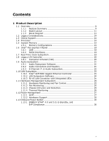
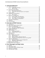
Intel Desktop Board DP55WG Technical Product Specification 17. Main Power Connector 47 18. Front Panel Header 48 19. States for a One-Color Power LED 49 20. States for a Two-Color Power LED 49 21. BIOS Setup Configuration Jumper Settings 52 22. Recommended Power Supply Current Values 54 23. Fan Header Current Capability 55 24. Thermal Considerations for Components 57 25. Environmental Specifications 58 26. BIOS Setup Program Menu Bar 60 27. BIOS Setup Program Function Keys 60 28. AcceptableDrives/Media Types for BIOS Recovery 63 29. Boot Device Menu Options 64 30. Supervisor and User Password Functions 66 31. BIOS Beep Codes 69 32. Front-panel Power LED Blink Codes 70 33. BIOS Error Messages 70 34. Port 80h POST Code Ranges 71 35. Port 80h POST Codes 72 36. Typical Port 80h POST Sequence 75 37. Safety Standards 77 38. Lead-Free Board Markings 82 39. EMC Regulations 83 40. Product Certification Markings 84 viii

  • 1
  • 2
  • 3
  • 4
  • 5
  • 6
  • 7
  • 8
  • 9
  • 10
  • 11
  • 12
  • 13
  • 14
  • 15
  • 16
  • 17
  • 18
  • 19
  • 20
  • 21
  • 22
  • 23
  • 24
  • 25
  • 26
  • 27
  • 28
  • 29
  • 30
  • 31
  • 32
  • 33
  • 34
  • 35
  • 36
  • 37
  • 38
  • 39
  • 40
  • 41
  • 42
  • 43
  • 44
  • 45
  • 46
  • 47
  • 48
  • 49
  • 50
  • 51
  • 52
  • 53
  • 54
  • 55
  • 56
  • 57
  • 58
  • 59
  • 60
  • 61
  • 62
  • 63
  • 64
  • 65
  • 66
  • 67
  • 68
  • 69
  • 70
  • 71
  • 72
  • 73
  • 74
  • 75
  • 76
  • 77
  • 78
  • 79
  • 80
  • 81
  • 82
  • 83
  • 84
  • 85
  • 86
  • 87
  • 88

Intel Desktop Board DP55WG Technical Product Specification
viii
17. Main Power Connector
......................................................................
47
18. Front Panel Header
..........................................................................
48
19. States for a One-Color Power LED
......................................................
49
20. States for a Two-Color Power LED
......................................................
49
21. BIOS Setup Configuration Jumper Settings
..........................................
52
22. Recommended Power Supply Current Values
.......................................
54
23. Fan Header Current Capability
...........................................................
55
24. Thermal Considerations for Components
.............................................
57
25. Environmental Specifications
.............................................................
58
26. BIOS Setup Program Menu Bar
..........................................................
60
27. BIOS Setup Program Function Keys
....................................................
60
28. AcceptableDrives/Media Types for BIOS Recovery
................................
63
29. Boot Device Menu Options
................................................................
64
30. Supervisor and User Password Functions
.............................................
66
31. BIOS Beep Codes
............................................................................
69
32. Front-panel Power LED Blink Codes
....................................................
70
33. BIOS Error Messages
.......................................................................
70
34. Port 80h POST Code Ranges
..............................................................
71
35. Port 80h POST Codes
.......................................................................
72
36. Typical Port 80h POST Sequence
........................................................
75
37. Safety Standards
.............................................................................
77
38. Lead-Free Board Markings
................................................................
82
39. EMC Regulations
.............................................................................
83
40. Product Certification Markings
...........................................................
84