Intel BLKDP55WG Product Specification - Page 12
Table 2., Components Shown
 |
UPC - 735858206044
View all Intel BLKDP55WG manuals
Add to My Manuals
Save this manual to your list of manuals |
Page 12 highlights
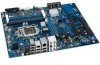
Intel Desktop Board DP55WG Technical Product Specification Table 2. Components Shown in Figure 1 Item/callout from Figure 1 Description A PCI bus connector B PCI Express 2.0 x4 connector C PCI bus connector D PCI Express 2.0 x8 connector E Front panel audio header F S/PDIF header G PCI Express 2.0 x1 connector H Rear chassis fan header I PCI Express 2.0 x1 connector J PCI Express 2.0 x16 connector K Battery L Back panel connectors M 12 V processor core voltage connector (2 x 4) N Processor fan header O Processor LED (red) P Voltage regulator LED (red) Q Processor socket R POST code LED display S DIMM Channel A socket T DIMM Channel B socket U Onboard power button V Standby power indicator LED (green) W Main power connector (2 x 12) X SATA drive activity LED (blue) Y Front panel header Z Back panel CIR emitter (output) header AA Front panel CIR receiver (input) header BB Alternate front panel power LED header CC Front chassis fan header DD USB 2.0 headers (2) EE IEEE 1394a header FF Intel P55 Express Chipset GG BIOS configuration jumper block HH Serial ATA connectors II Chassis intrusion header JJ USB 2.0 header KK Speaker LL Auxiliary PCI Express graphics power connector (SATA-style) 12
-
 1
1 -
2
-
3
-
4
-
5
-
6
-
 7
7 -
 8
8 -
 9
9 -
 10
10 -
 11
11 -
 12
12 -
 13
13 -
 14
14 -
 15
15 -
 16
16 -
 17
17 -
18
-
19
-
20
-
21
-
22
-
23
-
24
-
25
-
26
-
27
-
28
-
29
-
30
-
31
-
32
-
33
-
34
-
35
-
36
-
37
-
38
-
39
-
40
-
41
-
42
-
43
-
44
-
45
-
46
-
47
-
48
-
49
-
50
-
51
-
52
-
53
-
54
-
55
-
56
-
57
-
58
-
59
-
60
-
61
-
62
-
63
-
64
-
65
-
66
-
67
-
68
-
69
-
70
-
71
-
72
-
73
-
74
-
75
-
76
-
77
-
78
-
79
-
80
-
81
-
82
-
83
-
84
-
85
-
86
-
87
-
88
 |
 |
