Intel BLKDP55WG Product Specification - Page 18
Intel, P55 Express Chipset - drivers
 |
UPC - 735858206044
View all Intel BLKDP55WG manuals
Add to My Manuals
Save this manual to your list of manuals |
Page 18 highlights
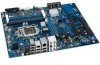
Intel Desktop Board DP55WG Technical Product Specification 1.6 Intel® P55 Express Chipset The Intel P55 Express Chipset consisting of the Intel P55 Express Platform Controller Hub (PCH) provides interfaces to the processor and the USB, SATA, LPC, LAN, PCI, and PCIe interfaces. The PCH is a centralized controller for the board's I/O paths. For information about The Intel P55 Express Chipset Resources used by the chipset Refer to http://www.intel.com/products/desktop/chipsets/index.htm Chapter 2 1.6.1 USB The board supports up to fourteen USB 2.0 ports, supports EHCI, and has two internal hubs (RMH) that allow the use of EHCI-compatible drivers. The PCH provides the USB controller for all ports. The port arrangement is as follows: • Eight ports are implemented with stacked back panel connectors • Three internal headers that support six additional ports For information about The location of the USB connectors on the back panel The location of the front panel USB headers Refer to Figure 10, page 40 Figure 11, page 41 1.6.2 SATA Interfaces The board provides six internal SATA connectors through the PCH, which support one device per connector. The PCH provides independent SATA ports with a theoretical maximum transfer rate of 3 Gb/s per port. One device can be installed on each port for a maximum of six SATA devices. A point-to-point interface is used for host to device connections, unlike Parallel ATA (PATA) IDE which supports a master/slave configuration and two devices per channel. For compatibility, the underlying SATA functionality is transparent to the operating system. The SATA controller can operate in both legacy and native modes. In legacy mode, standard IDE I/O and IRQ resources are assigned (IRQ 14 and 15). In Native mode, standard PCI Conventional bus resource steering is used. Native mode is the preferred mode for configurations using the Windows* XP, Windows Vista*, and Windows 7* operating systems. NOTE Many SATA drives use new low-voltage power connectors and require adapters or power supplies equipped with low-voltage power connectors. For more information, see: http://www.serialata.org/. For information about The location of the SATA connectors Refer to Figure 11, page 41 18
-
 1
1 -
2
-
3
-
4
-
5
-
6
-
7
-
8
-
9
-
10
-
11
-
12
-
 13
13 -
 14
14 -
 15
15 -
 16
16 -
 17
17 -
 18
18 -
 19
19 -
 20
20 -
 21
21 -
 22
22 -
 23
23 -
24
-
25
-
26
-
27
-
28
-
29
-
30
-
31
-
32
-
33
-
34
-
35
-
36
-
37
-
38
-
39
-
40
-
41
-
42
-
43
-
44
-
45
-
46
-
47
-
48
-
49
-
50
-
51
-
52
-
53
-
54
-
55
-
56
-
57
-
58
-
59
-
60
-
61
-
62
-
63
-
64
-
65
-
66
-
67
-
68
-
69
-
70
-
71
-
72
-
73
-
74
-
75
-
76
-
77
-
78
-
79
-
80
-
81
-
82
-
83
-
84
-
85
-
86
-
87
-
88
 |
 |
