Intel D101GGC Intel Desktop Board D101GGC Product Guide English
Intel D101GGC Manual
 |
View all Intel D101GGC manuals
Add to My Manuals
Save this manual to your list of manuals |
Intel D101GGC manual content summary:
- Intel D101GGC | Intel Desktop Board D101GGC Product Guide English - Page 1
Intel® Desktop Board D101GGC Product Guide Order Number: D34588-004 - Intel D101GGC | Intel Desktop Board D101GGC Product Guide English - Page 2
Intel® Desktop Board D101GGC Product Guide Second release of the Intel Desktop Board D101GGC Product Guide Third release of the Intel Desktop Board D101GGC Product Guide Fourth release of the Intel Desktop Board D101GGC Product Guide in accordance with the instructions, may cause harmful interference - Intel D101GGC | Intel Desktop Board D101GGC Product Guide English - Page 3
equipment, etc. may not be supported without further evaluation by Intel. Information Layout The chapters in this Product Guide are arranged as follows: 1 Desktop Board Features: a summary of product features 3 2 Installing and Replacing Desktop Board Components: instructions on how to install the - Intel D101GGC | Intel Desktop Board D101GGC Product Guide English - Page 4
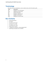
Intel Desktop Board D101GGC Product Guide Terminology The table below gives descriptions to some common terms used in the product guide. Term Description GB Gigabyte (1,073,741,824 bytes) GHz Gigahertz (one billion hertz) KB Kilobyte (1024 bytes) MB Megabyte (1,048,576 bytes) Mbit - Intel D101GGC | Intel Desktop Board D101GGC Product Guide English - Page 5
Contents 1 Desktop Board Features Supported Operating Systems 10 Desktop Board Components 11 Processor...13 Main Memory ...13 ATI RADEON* XPRESS 200 Chipset 14 Graphics Subsystem ...14 Audio Subsystem ...14 Input/Output (I/O) Controller 15 LAN Subsystem ...15 LAN Subsystem Software 15 RJ-45 LAN - Intel D101GGC | Intel Desktop Board D101GGC Product Guide English - Page 6
Board D101GGC Product Guide Installing and Removing Memory 31 Installing DIMMs...31 Removing DIMMs...33 Installing and Removing a PCI Express* x16 Card 34 Installing a PCI Express x16 Card 34 Removing the PCI Express x16 Card 34 Connecting the IDE Cable 35 Connecting the Serial ATA (SATA - Intel D101GGC | Intel Desktop Board D101GGC Product Guide English - Page 7
the Battery 50 Tables 1. Feature Summary ...9 2. Desktop Boards D101GGC Components 12 3. Power Supply Requirements 13 4. RJ-45 10/100 Ethernet LAN Connector LEDs 16 5. Front Panel Audio Header Signal Names for High Definition Audio 38 6. AC '97 Audio Header Signal Names 38 7. Hi-Speed USB - Intel D101GGC | Intel Desktop Board D101GGC Product Guide English - Page 8
Intel Desktop Board D101GGC Product Guide viii - Intel D101GGC | Intel Desktop Board D101GGC Product Guide English - Page 9
• Suspend to RAM (STR) • Wake on USB, PCI, PCI Express, PS/2, LAN, and front panel Related Links: For more information about desktop board D101GGC, including the Technical Product Specification (TPS), BIOS updates, and device drivers, go to: http://support.intel.com/support/motherboards/desktop/ 9 - Intel D101GGC | Intel Desktop Board D101GGC Product Guide English - Page 10
Intel Desktop Board D101GGC Product Guide Supported Operating Systems The desktop board supports the following operating systems: • Microsoft Windows* XP Media Center Edition 2005 • Microsoft Windows XP Professional • Microsoft Windows XP Professional x64 Edition • Microsoft Windows XP Home • - Intel D101GGC | Intel Desktop Board D101GGC Product Guide English - Page 11
Desktop Board Features Desktop Board Components Figure 1 shows the approximate location of the major components on desktop board D101GGC. Line In A BC D E W F G V H U T S DIMM 0 DIMM 1 I R J Q P ON M L K Figure 1. Intel Desktop Board D101GGC Components OM18207 11 - Intel D101GGC | Intel Desktop Board D101GGC Product Guide English - Page 12
Intel Desktop Board D101GGC Product Guide Table 2. Label A B C D E F G H I J K L M N O P Q R S T U V W Desktop Boards D101GGC Components Description PCI bus add-in card connectors Front panel audio header PCI Express* x1 connector PCI Express x16 connector Back panel connectors 12 V processor core - Intel D101GGC | Intel Desktop Board D101GGC Product Guide English - Page 13
the LGA775 socket. The supported processors list for desktop board D101GGC is located on the web at: http://support.intel.com/support/motherboards/desktop/ Related Links: Go to the following links or pages for more information about: • Instructions on installing or upgrading the processor, page 27 - Intel D101GGC | Intel Desktop Board D101GGC Product Guide English - Page 14
Intel Desktop Board D101GGC Product Guide Related Links: Go to the following links or pages for more information about: • The latest list of tested memory, http://support.intel.com/support/motherboards/desktop/ • SDRAM specifications, http://www.intel.com/technology/memory/ • Installing memory, page - Intel D101GGC | Intel Desktop Board D101GGC Product Guide English - Page 15
Desktop Board Features Related Links: Go to the following link or pages for more information about: • Audio drivers and utilities http://support.intel.com/support/motherboards/desktop/ • Installing the front panel audio solution, page 38 in Chapter 2 • The location of audio connectors, Figure 19 on - Intel D101GGC | Intel Desktop Board D101GGC Product Guide English - Page 16
Intel Desktop Board D101GGC Product Guide AB Figure 2. LAN Connector LEDs OM18208 Table 4 describes the LED states when the board is powered up and 2.0 support requires both an operating system and drivers that fully support USB 2.0 transfer rates. Disabling Hi-Speed USB in the BIOS reverts all - Intel D101GGC | Intel Desktop Board D101GGC Product Guide English - Page 17
. Expandability The desktop board supports the following: • One PCI Express x16 add-in card • One PCI Express x1 add-in card • Two PCI add-in cards Related Links: For information about installing the PCI Express x16 card, see page 34 in Chapter 2. BIOS The BIOS provides the Power-On Self-Test (POST - Intel D101GGC | Intel Desktop Board D101GGC Product Guide English - Page 18
Intel Desktop Board D101GGC Product Guide Security Passwords The BIOS includes security features that restrict whether the BIOS Setup program can be accessed and who can boot the computer. A supervisor password and a user password can be set for the BIOS Setup and for booting the computer, with the - Intel D101GGC | Intel Desktop Board D101GGC Product Guide English - Page 19
state) configuration. If the standby current necessary to support multiple wake events from the PCI and/or USB buses exceeds power supply capacity, the desktop board may lose register settings stored in memory. Instantly Available PC technology enables the board to enter the ACPI S3 (Suspend-to - Intel D101GGC | Intel Desktop Board D101GGC Product Guide English - Page 20
Intel Desktop Board D101GGC Product Guide CR1 OM18209 Figure 3. Location of the Standby Power Indicator Related Links: For more information on standby current requirements for the desktop board, refer to the Technical Product Specification by going to the following link, finding the product, and - Intel D101GGC | Intel Desktop Board D101GGC Product Guide English - Page 21
on the desktop board. The speaker provides audible error code (beep code) information during the Power-On Self-Test (POST). Battery A battery on the desktop board keeps the values in CMOS RAM and the clock current when the computer is turned off. Go to page 46 for instructions on how to replace - Intel D101GGC | Intel Desktop Board D101GGC Product Guide English - Page 22
Intel Desktop Board D101GGC Product Guide 22 - Intel D101GGC | Intel Desktop Board D101GGC Product Guide English - Page 23
and remove the desktop board • Install and remove a processor and memory • Install and remove a PCI Express x16 card • Connect the IDE and Serial ATA cables • Connect internal headers • Set up flexible 6-channel audio with jack re-tasking • Connect fans and power cables • Locate other connectors - Intel D101GGC | Intel Desktop Board D101GGC Product Guide English - Page 24
on the chassis • Hot components (like processors, voltage regulators, and heat sinks) • Damage to wires that could cause a short circuit Observe all warnings and cautions that instruct you to refer computer servicing to qualified technical personnel. Prevent Power Supply Overload Do not overload the - Intel D101GGC | Intel Desktop Board D101GGC Product Guide English - Page 25
Components Installing the I/O Shield The desktop board comes with an I/O shield. When installed in the chassis and promotes correct airflow within the chassis. Install the I/O shield before installing the desktop board in the chassis. Place the shield inside the chassis as shown in Figure 4. Press - Intel D101GGC | Intel Desktop Board D101GGC Product Guide English - Page 26
power before you open the computer can result in personal injury or equipment damage. Refer to your chassis manual for instructions on installing and removing the desktop board. Figure 5 shows the location of the mounting screw holes for desktop board D101GGC. OM18211 Figure 5. Desktop Board D101GGC - Intel D101GGC | Intel Desktop Board D101GGC Product Guide English - Page 27
the computer; the standby power LED should not be lit (see Figure 3 on page 20). Failure to do so could damage the processor and the board. To install a processor, follow these instructions: 1. Observe the precautions in "Before You Begin" on page 23. 2. Open the socket lever by pushing the lever - Intel D101GGC | Intel Desktop Board D101GGC Product Guide English - Page 28
Intel Desktop Board D101GGC Product Guide 4. Remove the plastic protective socket cover from the load plate (see Figure 8, E). Do not discard the protective socket cover. Always replace the socket cover if the processor is removed from the socket. E OM17228 Figure 8. Remove the Protective Socket - Intel D101GGC | Intel Desktop Board D101GGC Product Guide English - Page 29
and Replacing Desktop Board Components 6. Hold the processor with your thumb and index fingers oriented as shown in Figure 10. Make sure fingers align to the socket cutouts (see Figure 10, F). Align notches (see Figure 10, G) with the socket see (Figure 10, H). Lower the processor straight down - Intel D101GGC | Intel Desktop Board D101GGC Product Guide English - Page 30
Product Guide Installing the Processor Fan Heat Sink Desktop board D101GGC has an integrated processor fan heat sink retention mechanism (RM). For instructions on how to attach the processor fan heat sink to the integrated processor fan heat sink RM, refer to the boxed processor manual or the Intel - Intel D101GGC | Intel Desktop Board D101GGC Product Guide English - Page 31
Detect Specification at: http://www.intel.com/technology/memory/ddr/specs/dda18c32_64_128x72ag_a.pdf The desktop board has two 184-pin DIMM sockets arranged as DIMM 0 (blue) and DIMM 1 (black). Installing DIMMs NOTE Install memory in the DIMM sockets prior to installing the PCI Express video card to - Intel D101GGC | Intel Desktop Board D101GGC Product Guide English - Page 32
Intel Desktop Board D101GGC Product Guide 1. Observe the precautions in "Before You Begin" on page 23. 2. Turn off all peripheral devices connected to the computer. Turn off the computer and disconnect the AC power cord. 3. Remove the computer's cover and locate the DIMM sockets (see Figure 14). A - Intel D101GGC | Intel Desktop Board D101GGC Product Guide English - Page 33
from the socket, and store it in an anti-static package. 8. Reinstall the PCI Express card if you removed it before taking out the DIMM. 9. Reinstall and reconnect any parts you removed or disconnected to reach the DIMM sockets. 10. Replace the computer's cover and reconnect the AC power cord. 33 - Intel D101GGC | Intel Desktop Board D101GGC Product Guide English - Page 34
Intel Desktop Board D101GGC Product Guide Installing and Removing a PCI Express* x16 Card CAUTION When installing a PCI Express x16 card on the desktop board, ensure that it is fully seated in the PCI Express x16 connector before you power on the system. If the card is not fully seated in the PCI - Intel D101GGC | Intel Desktop Board D101GGC Product Guide English - Page 35
to the desktop board. The cable supports the ATA-100 transfer protocol are attached to the same cable, the maximum transfer rate between the drives may be reduced to that the cable end with the single connector (blue) to the Intel desktop board (Figure 16). • Attach the cable end with the two - Intel D101GGC | Intel Desktop Board D101GGC Product Guide English - Page 36
Intel Desktop Board D101GGC Product Guide Connecting the Serial ATA (SATA) Cable The SATA cable (4-conductor) supports the Serial ATA protocol and connects a single drive to the desktop board. Either end of the cable can be connected to the SATA drive or the connector on the board. For correct cable - Intel D101GGC | Intel Desktop Board D101GGC Product Guide English - Page 37
# Port2R 5 6 Sense1_Ret Sense_Send 7 Key (no pin) Port2L 9 10 Sense2_Ret C HD LED Reset +5 V - + 12 34 56 78 9 - + Power LED On/Off Item A B C D Description Hi-speed USB 2.0 (two) Alternate front panel power LED Front panel Front panel audio Figure 18. Internal Headers OM18217 37 - Intel D101GGC | Intel Desktop Board D101GGC Product Guide English - Page 38
Intel Desktop Board D101GGC Product Guide Installing a Front Panel Audio Solution for High Definition Audio Figure 18, D on page 37 shows the location of the yellow front panel audio header. Table 5 shows the pin assignments for the front panel audio header. Table 5. Front Panel Audio Header - Intel D101GGC | Intel Desktop Board D101GGC Product Guide English - Page 39
Installing and Replacing Desktop Board Components Connecting Hi-Speed USB 2.0 Headers Before connecting the Signal Names Pin Signal In/Out Description Pin Signal In/Out Description Hard Drive Activity LED Power LED 1 HD_PWR Out Hard disk LED pullup (330 Ω) to +5 V 2 HDR_BLNK_GRN Out - Intel D101GGC | Intel Desktop Board D101GGC Product Guide English - Page 40
Intel Desktop Board D101GGC Product Guide Setting Up the Flexible 6-Channel Audio with Jack Re-tasking (Optional) After installing the Realtek audio driver, the multi-channel audio feature can be enabled. A B C Item A B C Description Rear left/right out or Line In Front left/right out or Line - Intel D101GGC | Intel Desktop Board D101GGC Product Guide English - Page 41
Installing and Replacing Desktop Board Components Connecting Fan and Power Cables Connecting Fan Cables Figure 20 shows the location of the fan headers. Connect the processor's fan heat sink cable to the 4-pin processor fan header on the board. Connect chassis fan cables to the 3-pin fan headers. 3 - Intel D101GGC | Intel Desktop Board D101GGC Product Guide English - Page 42
Intel Desktop Board D101GGC Product Guide Connecting Power Cables CAUTION Failure to use the appropriate power supply and/or not connecting the 12 V (2x2) power connector to the desktop board may result in damage to the board or the system may not function properly. See Table 3 on page 13 for power - Intel D101GGC | Intel Desktop Board D101GGC Product Guide English - Page 43
intrusion, and diskette drive connectors. ABC Item A B C D E E Description PCI bus add-in card connector 2 PCI bus add-in card connector 1 PCI Express x1 connector Chassis intrusion connector Diskette drive connector D OM18221 Figure 22. Location of Other Connectors on Desktop Board D101GGC 43 - Intel D101GGC | Intel Desktop Board D101GGC Product Guide English - Page 44
Intel Desktop Board D101GGC Product Guide Setting the BIOS Configuration Jumper NOTE Always turn off the power and unplug the power cord from the computer before changing the jumper. Moving the jumper with the power on may result in unreliable computer operation. Figure 23 shows the location of the - Intel D101GGC | Intel Desktop Board D101GGC Product Guide English - Page 45
-Test (POST) runs, the BIOS 1 displays the Maintenance Menu. Use this menu to clear passwords. 3 Recovery (None) The BIOS recovers data from a recovery diskette in the 1 event of a failed BIOS update. 3 Clearing Passwords This procedure assumes that the board is installed in the computer - Intel D101GGC | Intel Desktop Board D101GGC Product Guide English - Page 46
Board D101GGC Product Guide Replacing the Battery A coin-cell battery (CR2032) powers the real-time clock and CMOS memory. When the computer is not plugged into a wall socket, the battery has an estimated life of three years. When the computer is plugged in, the standby current from the power supply - Intel D101GGC | Intel Desktop Board D101GGC Product Guide English - Page 47
Installing and Replacing Desktop Board Components AVVERTIMENTO Esiste il pericolo di un esplosione se la pila non viene sostituita in modo corretto. Utilizzare solo pile uguali o di tipo equivalente a quelle - Intel D101GGC | Intel Desktop Board D101GGC Product Guide English - Page 48
Intel Desktop Board D101GGC Product Guide AWAS Risiko letupan wujud jika bateri digantikan dengan jenis yang tidak betul. Bateri sepatutnya dikitar semula jika boleh. Pelupusan bateri terpakai mestilah mematuhi peraturan alam - Intel D101GGC | Intel Desktop Board D101GGC Product Guide English - Page 49
Installing and Replacing Desktop Board Components O 49 - Intel D101GGC | Intel Desktop Board D101GGC Product Guide English - Page 50
Intel Desktop Board D101GGC Product Guide To replace the battery, follow these steps: 1. Observe the precautions in "Before You Begin" (see page 23). 2. Turn off all peripheral devices connected to the computer. Disconnect the computer's power cord from the AC power source (wall outlet or power - Intel D101GGC | Intel Desktop Board D101GGC Product Guide English - Page 51
(EMC) regulations • Product certifications Safety Regulations Desktop board D101GGC complies with the safety regulations stated in Table 10 Place Battery Marking There is insufficient space on this desktop board to provide instructions for replacing and disposing of the Lithium ion coin cell - Intel D101GGC | Intel Desktop Board D101GGC Product Guide English - Page 52
Intel Desktop Board D101GGC Product Guide European Union Declaration of Conformity Statement We, Intel Corporation, declare under our sole responsibility that the product Intel® Desktop Board D101GGC is in conformity with all applicable essential requirements necessary for CE marking, following the - Intel D101GGC | Intel Desktop Board D101GGC Product Guide English - Page 53
.htm for the details of this program, including the scope of covered products, available locations, shipping instructions, terms and conditions, etc. 中文 Intel Product Recycling Program 请参考http://www.intel.com/intel/other/ehs/product_ecology/Recycling_Program.htm Deutsch Als Teil von - Intel D101GGC | Intel Desktop Board D101GGC Product Guide English - Page 54
Intel Desktop Board D101GGC Product Guide Français Dans le cadre de son engagement pour la protection de l'environnement, Intel a mis en œuvre le programme Intel Product Recycling Program (Programme de recyclage des produits Intel) pour permettre aux consommateurs de produits Intel de recycler les - Intel D101GGC | Intel Desktop Board D101GGC Product Guide English - Page 55
ayrıntılarını ögrenmek için lütfen http://www.intel.com/intel/other/ehs/product_ecology/Recycling_Program.htm web sayfasına gidin. Lead-Free Desktop Board This desktop board is lead free although certain discrete components used on the board contain a small amount of lead which is necessary for - Intel D101GGC | Intel Desktop Board D101GGC Product Guide English - Page 56
Intel Desktop Board D101GGC Product Guide EMC Regulations Desktop board D101GGC complies with the EMC regulations stated in 3rd Edition, (Class B) CISPR 24: 1997 VCCI (Class B) Title Title 47 of the Code of Federal Regulations, Parts 2 and 15, Subpart B, Radio Frequency Devices. (USA) Interference- - Intel D101GGC | Intel Desktop Board D101GGC Product Guide English - Page 57
radio interference. Install and use the equipment according to the instruction manual. Korean Class B statement translation: This is household equipment attention to the following when reading the installation instructions for the chassis, power supply, and other modules: • Product certifications or - Intel D101GGC | Intel Desktop Board D101GGC Product Guide English - Page 58
. For information about MIC certification, go to http://support.intel.com/support/motherboards/desktop/ Taiwan BSMI (Bureau of Standards, Metrology and Inspections) mark. Includes adjacent Intel company number, D33025. Printed wiring board manufacturer's recognition mark. Consists of a unique UL - Intel D101GGC | Intel Desktop Board D101GGC Product Guide English - Page 59
Component Certifications Ensure that the chassis and certain components; such as the power supply, peripheral drives, wiring, and cables; are components certified for the country Industry Canada statement at the front of this product guide demonstrates compliance with Canadian EMC regulations. 59 - Intel D101GGC | Intel Desktop Board D101GGC Product Guide English - Page 60
Intel Desktop Board D101GGC Product Guide 60
-
 1
1 -
 2
2 -
 3
3 -
 4
4 -
 5
5 -
 6
6 -
 7
7 -
8
-
9
-
10
-
11
-
12
-
13
-
14
-
15
-
16
-
17
-
18
-
19
-
20
-
21
-
22
-
23
-
24
-
25
-
26
-
27
-
28
-
29
-
30
-
31
-
32
-
33
-
34
-
35
-
36
-
37
-
38
-
39
-
40
-
41
-
42
-
43
-
44
-
45
-
46
-
47
-
48
-
49
-
50
-
51
-
52
-
53
-
54
-
55
-
56
-
57
-
58
-
59
-
60
 |
 |
Intel® Desktop Board D101GGC
Product Guide
Order Number:
D34588-004