Intel D101GGC Intel Desktop Board D101GGC Product Guide English - Page 29
Install Processor, Close the Load Plate
 |
View all Intel D101GGC manuals
Add to My Manuals
Save this manual to your list of manuals |
Page 29 highlights
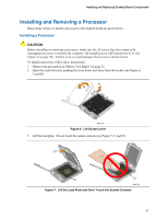
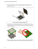
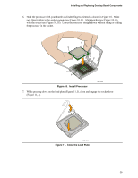
Installing and Replacing Desktop Board Components 6. Hold the processor with your thumb and index fingers oriented as shown in Figure 10. Make sure fingers align to the socket cutouts (see Figure 10, F). Align notches (see Figure 10, G) with the socket see (Figure 10, H). Lower the processor straight down without tilting or sliding the processor in the socket. G G H F H F Figure 10. Install Processor OM17214 7. While pressing down on the load plate (Figure 11, I), close and engage the socket lever (Figure 11, J). J I OM17215 Figure 11. Close the Load Plate 29
-
 1
1 -
2
-
3
-
4
-
5
-
6
-
7
-
8
-
9
-
10
-
11
-
12
-
13
-
14
-
15
-
16
-
17
-
18
-
19
-
20
-
21
-
22
-
23
-
 24
24 -
 25
25 -
 26
26 -
 27
27 -
 28
28 -
 29
29 -
 30
30 -
 31
31 -
 32
32 -
 33
33 -
 34
34 -
35
-
36
-
37
-
38
-
39
-
40
-
41
-
42
-
43
-
44
-
45
-
46
-
47
-
48
-
49
-
50
-
51
-
52
-
53
-
54
-
55
-
56
-
57
-
58
-
59
-
60
 |
 |
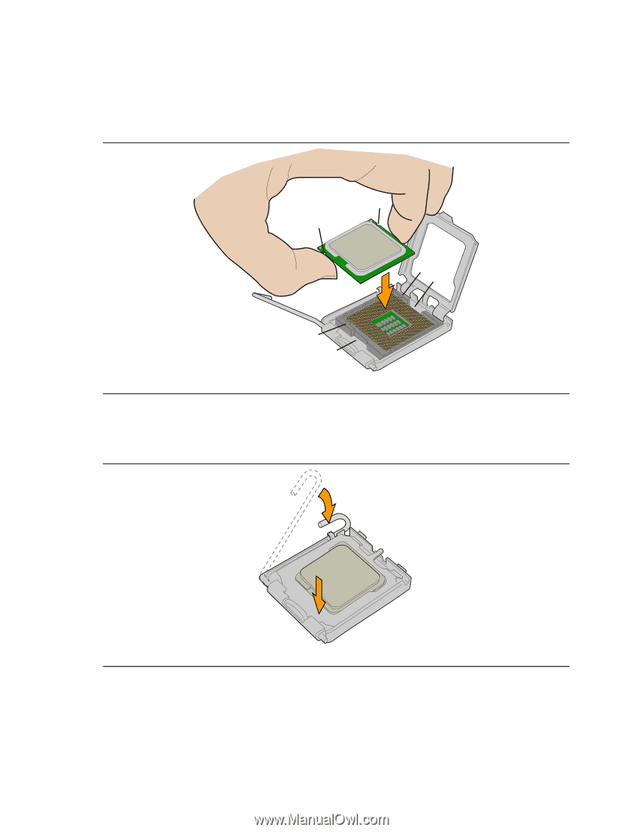
Installing and Replacing Desktop Board Components
29
6.
Hold the processor with your thumb and index fingers oriented as shown in Figure 10.
Make
sure fingers align to the socket cutouts (see Figure 10, F).
Align notches (see Figure 10, G)
with the socket see (Figure 10, H).
Lower the processor straight down without tilting or sliding
the processor in the socket.
OM17214
G
G
F
H
F
H
Figure 10.
Install Processor
7.
While pressing down on the load plate (Figure 11, I), close and engage the socket lever
(Figure 11, J).
OM17215
I
J
Figure 11.
Close the Load Plate