Intel D101GGC Intel Desktop Board D101GGC Product Guide English - Page 7

Tables - power supply

Page 7 highlights

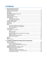
Contents 17. Connecting the Serial ATA Cable 36 18. Internal Headers ...37 19. Back Panel Audio Connectors for Flexible 6-Channel Audio System 40 20. Location of Fan Headers 41 21. Connecting 2x12 Power Supply Cables 42 22. Location of Other Connectors on Desktop Board D101GGC 43 23. Location of the BIOS Configuration Jumper Block 44 24. Removing the Battery 50 Tables 1. Feature Summary ...9 2. Desktop Boards D101GGC Components 12 3. Power Supply Requirements 13 4. RJ-45 10/100 Ethernet LAN Connector LEDs 16 5. Front Panel Audio Header Signal Names for High Definition Audio 38 6. AC '97 Audio Header Signal Names 38 7. Hi-Speed USB 2.0 Header Signal Names 39 8. Front Panel Header Signal Names 39 9. Jumper Settings for the BIOS Setup Program Modes 45 10. Safety Regulations...51 11. Lead-Free Board Markings 55 12. EMC Regulations...56 13. Product Certification Markings 58 vii

  • 1
  • 2
  • 3
  • 4
  • 5
  • 6
  • 7
  • 8
  • 9
  • 10
  • 11
  • 12
  • 13
  • 14
  • 15
  • 16
  • 17
  • 18
  • 19
  • 20
  • 21
  • 22
  • 23
  • 24
  • 25
  • 26
  • 27
  • 28
  • 29
  • 30
  • 31
  • 32
  • 33
  • 34
  • 35
  • 36
  • 37
  • 38
  • 39
  • 40
  • 41
  • 42
  • 43
  • 44
  • 45
  • 46
  • 47
  • 48
  • 49
  • 50
  • 51
  • 52
  • 53
  • 54
  • 55
  • 56
  • 57
  • 58
  • 59
  • 60

Contents
vii
17. Connecting the Serial ATA Cable
.................................................................................
36
18. Internal Headers
...........................................................................................................
37
19. Back Panel Audio Connectors for Flexible 6-Channel Audio System
............................
40
20. Location of Fan Headers
...............................................................................................
41
21. Connecting 2x12 Power Supply Cables
........................................................................
42
22. Location of Other Connectors on Desktop Board D101GGC
.........................................
43
23. Location of the BIOS Configuration Jumper Block
........................................................
44
24. Removing the Battery
...................................................................................................
50
Tables
1.
Feature Summary
...........................................................................................................
9
2.
Desktop Boards D101GGC Components
......................................................................
12
3.
Power Supply Requirements
.........................................................................................
13
4.
RJ-45 10/100 Ethernet LAN Connector LEDs
...............................................................
16
5.
Front Panel Audio Header Signal Names for High Definition Audio
...............................
38
6.
AC ’97 Audio Header Signal Names
.............................................................................
38
7.
Hi-Speed USB 2.0 Header Signal Names
.....................................................................
39
8.
Front Panel Header Signal Names
................................................................................
39
9.
Jumper Settings for the BIOS Setup Program Modes
...................................................
45
10.
Safety Regulations
........................................................................................................
51
11.
Lead-Free Board Markings
...........................................................................................
55
12.
EMC Regulations
..........................................................................................................
56
13.
Product Certification Markings
......................................................................................
58