Intel D101GGC Intel Desktop Board D101GGC Product Guide English - Page 37
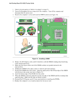
Connecting Internal Headers
 |
View all Intel D101GGC manuals
Add to My Manuals
Save this manual to your list of manuals |
Page 37 highlights
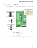
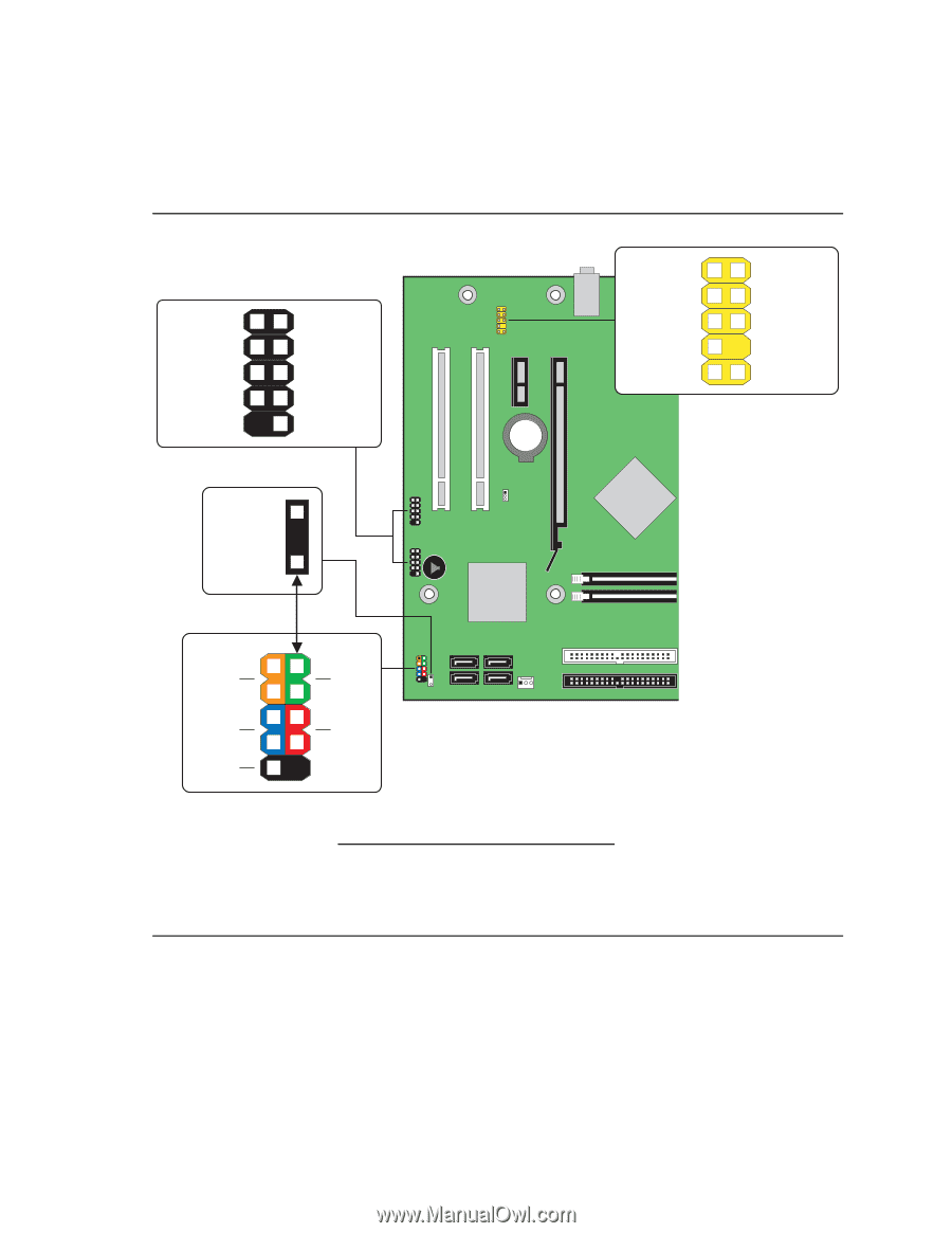
Installing and Replacing Desktop Board Components Connecting Internal Headers Before connecting cables to the internal headers, observe the precautions in "Before You Begin" on page 23. Figure 18 shows the location of the internal headers. A Power (+5 V) 1 2 Power (+5 V) D- 3 4 D- D+ 5 6 D+ Ground 7 8 Ground Key (no pin) 10 No Connection B +1 Alternate Front Panel Power LED -3 D Port1L 1 2 GND Port1R 3 4 Presence# Port2R 5 6 Sense1_Ret Sense_Send 7 Key (no pin) Port2L 9 10 Sense2_Ret C HD LED Reset +5 V - + 12 34 56 78 9 - + Power LED On/Off Item A B C D Description Hi-speed USB 2.0 (two) Alternate front panel power LED Front panel Front panel audio Figure 18. Internal Headers OM18217 37
-
 1
1 -
2
-
3
-
4
-
5
-
6
-
7
-
8
-
9
-
10
-
11
-
12
-
13
-
14
-
15
-
16
-
17
-
18
-
19
-
20
-
21
-
22
-
23
-
24
-
25
-
26
-
27
-
28
-
29
-
30
-
31
-
 32
32 -
 33
33 -
 34
34 -
 35
35 -
 36
36 -
 37
37 -
 38
38 -
 39
39 -
 40
40 -
 41
41 -
 42
42 -
43
-
44
-
45
-
46
-
47
-
48
-
49
-
50
-
51
-
52
-
53
-
54
-
55
-
56
-
57
-
58
-
59
-
60
 |
 |
Installing and Replacing Desktop Board Components
37
Connecting Internal Headers
Before connecting cables to the internal headers, observe the precautions in "Before You Begin" on
page 23.
Figure 18 shows the location of the internal headers.
OM18217
A
C
+5 V
Reset
HD LED
–
On/Off
Power
LED
+
+
–
9
8
7
6
5
4
2
3
1
B
Alternate
Front Panel
Power LED
10
8
7
6
5
4
2
1
3
No
Connection
Ground
D+
D–
Power (+5 V)
Key (no pin)
Ground
D+
Power (+5 V)
D–
3
+
–
1
D
10
9
7
6
5
4
2
1
3
Sense2_Ret
Key (no pin)
Sense1_Ret
Presence#
GND
Port2L
Sense_Send
Port2R
Port1R
Port1L
Item
Description
A
Hi-speed USB 2.0 (two)
B
Alternate front panel power LED
C
Front panel
D
Front panel audio
Figure 18.
Internal Headers