Intel D101GGC Intel Desktop Board D101GGC Product Guide English - Page 41
Connecting Fan and Power Cables
 |
View all Intel D101GGC manuals
Add to My Manuals
Save this manual to your list of manuals |
Page 41 highlights
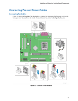
Installing and Replacing Desktop Board Components Connecting Fan and Power Cables Connecting Fan Cables Figure 20 shows the location of the fan headers. Connect the processor's fan heat sink cable to the 4-pin processor fan header on the board. Connect chassis fan cables to the 3-pin fan headers. 3 2 1 4 321 321 321 3 2 1 4 321 Figure 20. Location of Fan Headers 4 21 OM18219 41
-
 1
1 -
2
-
3
-
4
-
5
-
6
-
7
-
8
-
9
-
10
-
11
-
12
-
13
-
14
-
15
-
16
-
17
-
18
-
19
-
20
-
21
-
22
-
23
-
24
-
25
-
26
-
27
-
28
-
29
-
30
-
31
-
32
-
33
-
34
-
35
-
 36
36 -
 37
37 -
 38
38 -
 39
39 -
 40
40 -
 41
41 -
 42
42 -
 43
43 -
 44
44 -
 45
45 -
 46
46 -
47
-
48
-
49
-
50
-
51
-
52
-
53
-
54
-
55
-
56
-
57
-
58
-
59
-
60
 |
 |

Installing and Replacing Desktop Board Components
41
Connecting Fan and Power Cables
Connecting Fan Cables
Figure 20 shows the location of the fan headers.
Connect the processor’s fan heat sink cable to the
4-pin processor fan header on the board.
Connect chassis fan cables to the 3-pin fan headers.
OM18219
2
1
3
2
1
3
2
1
3
2
1
3
3
1
4
2
1
4
2
3
1
4
2
Figure 20.
Location of Fan Headers