Intel D101GGC Intel Desktop Board D101GGC Product Guide English - Page 39
Connecting Hi-Speed USB 2.0 Headers, Connecting the Front Panel Header
 |
View all Intel D101GGC manuals
Add to My Manuals
Save this manual to your list of manuals |
Page 39 highlights
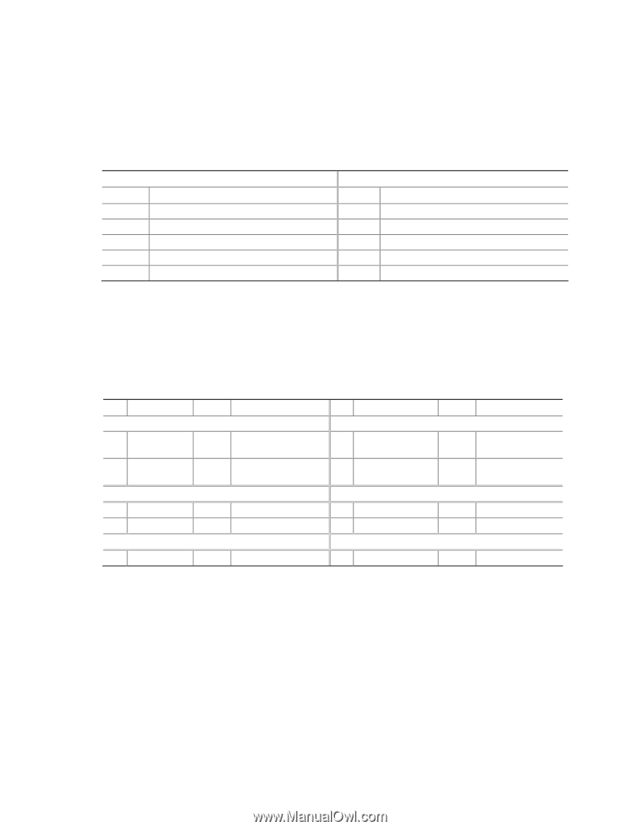
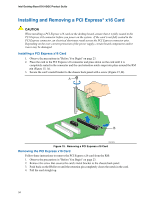
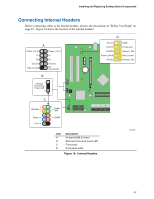
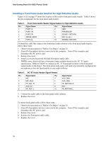
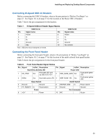
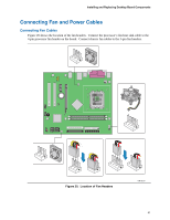
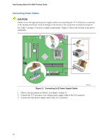
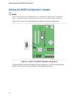
Installing and Replacing Desktop Board Components Connecting Hi-Speed USB 2.0 Headers Before connecting the USB 2.0 headers, observe the precautions in "Before You Begin" on page 23. See Figure 18, A on page 37 for the location of the black USB 2.0 headers. Table 7 shows the pin assignments for the headers. Table 7. Hi-Speed USB 2.0 Header Signal Names USB Port A Pin Signal name Pin 1 Power 2 3 D- 4 5 D+ 6 7 Ground 8 9 Key 10 Note: USB ports may be assigned as needed. USB Port B Signal name Power DD+ Ground No connect Connecting the Front Panel Header Before connecting the front panel header, observe the precautions in "Before You Begin" on page 23. See Figure 18, C on page 37 for the location of the multi-colored front panel header. Table 8 shows the pin assignments for the front panel header. Table 8. Front Panel Header Signal Names Pin Signal In/Out Description Pin Signal In/Out Description Hard Drive Activity LED Power LED 1 HD_PWR Out Hard disk LED pullup (330 Ω) to +5 V 2 HDR_BLNK_GRN Out Front panel green LED 3 HDA# Out Hard disk active LED 4 HDR_BLNK_YEL Out Front panel yellow LED Reset Switch On/Off Switch 5 Ground 7 FP_RESET# In Ground Reset switch 6 SWITCH_ON# In 8 Ground Power switch Ground Power Not Connected 9 +5 V Power 10 N/C No pin 39
-
 1
1 -
2
-
3
-
4
-
5
-
6
-
7
-
8
-
9
-
10
-
11
-
12
-
13
-
14
-
15
-
16
-
17
-
18
-
19
-
20
-
21
-
22
-
23
-
24
-
25
-
26
-
27
-
28
-
29
-
30
-
31
-
32
-
33
-
 34
34 -
 35
35 -
 36
36 -
 37
37 -
 38
38 -
 39
39 -
 40
40 -
 41
41 -
 42
42 -
 43
43 -
 44
44 -
45
-
46
-
47
-
48
-
49
-
50
-
51
-
52
-
53
-
54
-
55
-
56
-
57
-
58
-
59
-
60
 |
 |