Intel D201GLY2 Product Guide - Page 16
LAN Subsystem Software, RJ-45 LAN Connector LEDs, - driver
 |
UPC - 735858197717
View all Intel D201GLY2 manuals
Add to My Manuals
Save this manual to your list of manuals |
Page 16 highlights
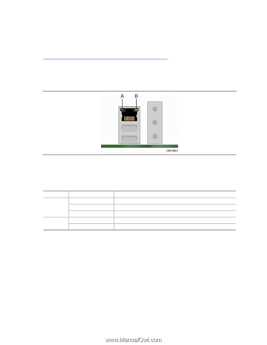
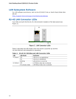
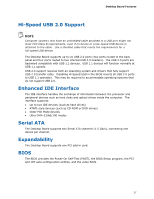
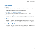
Intel Desktop Board D201GLY2 Product Guide LAN Subsystem Software For LAN software and drivers, refer to the D201GLY2 link on Intel's World Wide Web site at: http://support.intel.com/support/motherboards/desktop RJ-45 LAN Connector LEDs Two LEDs are built into the RJ-45 LAN connector located on the back panel (see Figure 3). Figure 3. LAN Connector LEDs Table 3 describes the LED states when the board is powered up and the 10/100 Ethernet LAN subsystem is operating. Table 3. RJ-45 10/100 Ethernet LAN Connector LEDs LED A (Green) B (Yellow) LED State Off On Blinking Off On (steady state) Indicates LAN link is not established LAN link is established LAN activity is occurring 10 Mbits/s data rate is selected 100 Mbits/s data rate is selected 16
-
 1
1 -
2
-
3
-
4
-
5
-
6
-
7
-
8
-
9
-
10
-
 11
11 -
 12
12 -
 13
13 -
 14
14 -
 15
15 -
 16
16 -
 17
17 -
 18
18 -
 19
19 -
 20
20 -
 21
21 -
22
-
23
-
24
-
25
-
26
-
27
-
28
-
29
-
30
-
31
-
32
-
33
-
34
-
35
-
36
-
37
-
38
-
39
-
40
-
41
-
42
-
43
-
44
-
45
-
46
-
47
-
48
-
49
-
50
-
51
-
52
-
53
-
54
-
55
-
56
-
57
-
58
-
59
-
60
-
61
 |
 |