Intel D201GLY2 Product Guide - Page 19
ACPI, Hardware Support, +5 V Standby Power Indicator LED, Power Connectors, Fan Headers
 |
UPC - 735858197717
View all Intel D201GLY2 manuals
Add to My Manuals
Save this manual to your list of manuals |
Page 19 highlights
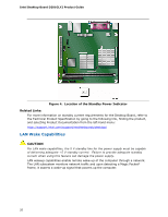
Desktop Board Features ACPI ACPI gives the operating system direct control over the power management and Plug and Play functions of a computer. The use of ACPI with the Desktop Board requires an operating system that provides full ACPI support. Hardware Support Power Connectors The Desktop Board has two power connectors. See Figure 13 on page 36 for the location of the power connectors. Fan Headers The Desktop Board has a 3-pin processor fan header and a 3-pin chassis fan header. See Figure 12 on page 35 for the location of the chassis fan header. +5 V Standby Power Indicator LED CAUTION If the AC power has been switched off and the standby power indicator is still lit, disconnect the power cord before installing or removing any devices connected to the board. Failure to do so could damage the board and any attached devices. The Desktop Board's standby power indicator, shown in Figure 4, is lit when there is standby power to the system. This includes the DIMM socket and the PCI bus connector, even though the computer appears to be off. 19
-
 1
1 -
2
-
3
-
4
-
5
-
6
-
7
-
8
-
9
-
10
-
11
-
12
-
13
-
 14
14 -
 15
15 -
 16
16 -
 17
17 -
 18
18 -
 19
19 -
 20
20 -
 21
21 -
 22
22 -
 23
23 -
 24
24 -
25
-
26
-
27
-
28
-
29
-
30
-
31
-
32
-
33
-
34
-
35
-
36
-
37
-
38
-
39
-
40
-
41
-
42
-
43
-
44
-
45
-
46
-
47
-
48
-
49
-
50
-
51
-
52
-
53
-
54
-
55
-
56
-
57
-
58
-
59
-
60
-
61
 |
 |