Intel D201GLY2 Product Guide - Page 38
BIOS Configuration Jumper, Table 7. Front Panel Audio Header/Jumper Block - bios update
 |
UPC - 735858197717
View all Intel D201GLY2 manuals
Add to My Manuals
Save this manual to your list of manuals |
Page 38 highlights
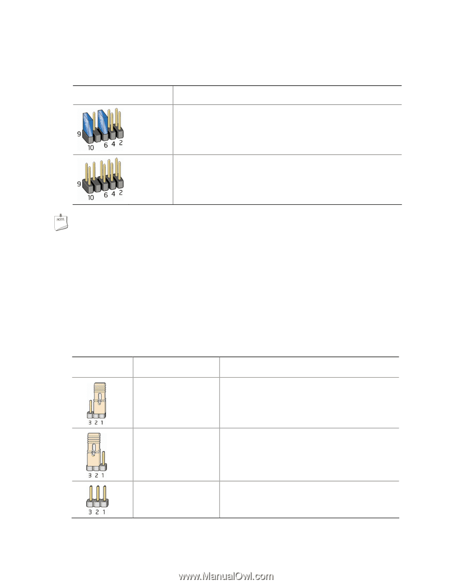
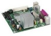
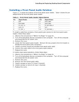
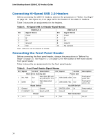
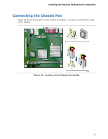
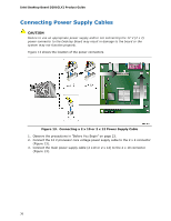
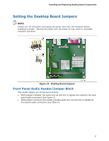
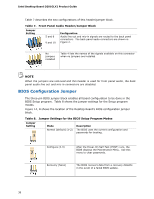
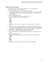
Intel Desktop Board D201GLY2 Product Guide Table 7 describes the two configurations of this header/jumper block. Table 7. Front Panel Audio Header/Jumper Block Jumper Setting 5 and 6 9 and 10 Configuration Audio line out and mic-in signals are routed to the back panel connectors. The back panel audio connectors are shown in Figure 2. No jumpers installed Table 4 lists the names of the signals available on this connector when no jumpers are installed. NOTE When the jumpers are removed and this header is used for front panel audio, the back panel audio line out and mic-in connectors are disabled. BIOS Configuration Jumper The three-pin BIOS jumper block enables all board configuration to be done in the BIOS Setup program. Table 8 shows the jumper settings for the Setup program modes. Figure 14, B shows the location of the Desktop Board's BIOS configuration jumper block. Table 8. Jumper Settings for the BIOS Setup Program Modes Jumper Setting Mode Normal (default) (1-2) Description The BIOS uses the current configuration and passwords for booting. Configure (2-3) After the Power-On Self-Test (POST) runs, the BIOS displays the Maintenance Menu. Use this menu to clear passwords. Recovery (None) The BIOS recovers data from a recovery diskette in the event of a failed BIOS update. 38
-
 1
1 -
2
-
3
-
4
-
5
-
6
-
7
-
8
-
9
-
10
-
11
-
12
-
13
-
14
-
15
-
16
-
17
-
18
-
19
-
20
-
21
-
22
-
23
-
24
-
25
-
26
-
27
-
28
-
29
-
30
-
31
-
32
-
 33
33 -
 34
34 -
 35
35 -
 36
36 -
 37
37 -
 38
38 -
 39
39 -
 40
40 -
 41
41 -
 42
42 -
 43
43 -
44
-
45
-
46
-
47
-
48
-
49
-
50
-
51
-
52
-
53
-
54
-
55
-
56
-
57
-
58
-
59
-
60
-
61
 |
 |