Intel D2550MUD2 Technical product specification - Page 22
SATA Support - bios update
 |
View all Intel D2550MUD2 manuals
Add to My Manuals
Save this manual to your list of manuals |
Page 22 highlights
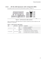
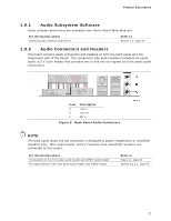
Intel Desktop Board D2550MUD2 Technical Product Specification NOTE Support for flat panel display configuration complies with the following: 1. Internal flat panel display connectivity is disabled (and all parameters hidden) by default. 2. Internal flat panel display settings are not exposed through Intel® Integrator Toolkit or Intel® Integrator Assistant GUIs. 3. Internal flat panel display settings will not be overwritten by loading BIOS setup defaults. 4. Internal flat panel display settings will be preserved across BIOS updates. 1.5.2 USB The board provides up to seven USB 2.0 ports, supports UHCI and EHCI, and uses UHCI- and EHCI-compatible drivers (four ports routed to the back panel and three ports routed to two front panel USB 2.0 headers). One of the front panel USB headers (brown-colored) supports an Intel Z-U130 USB Solid-State Drive or compatible device. NOTE Computer systems that have an unshielded cable attached to a USB port may not meet FCC Class B requirements, even if no device is attached to the cable. Use shielded cable that meets the requirements for full-speed devices. For information about The location of the USB connectors on the back panel The location of the front panel USB headers Refer to Figure 9, page 41 Figure 11, page 43 1.5.3 SATA Support The board provides two SATA interface connectors that support one device per connector. The board's SATA controller offers independent SATA ports with a theoretical maximum transfer rate of 3.0 Gb/s on each port. One device can be installed on each port for a maximum of two SATA devices. A point-to-point interface is used for host to device connections, unlike PATA which supports a master/slave configuration and two devices on each channel. For compatibility, the underlying SATA functionality is transparent to the operating system. The SATA controller supports IDE and AHCI configuration and can operate in both legacy and native modes. In legacy mode, standard ATA I/O and IRQ resources are assigned (IRQ 14 and 15). In native mode, standard Conventional PCI bus resource steering is used. Native mode is the preferred mode for configurations using the Windows Vista* operating system. 22
-
 1
1 -
2
-
3
-
4
-
5
-
6
-
7
-
8
-
9
-
10
-
11
-
12
-
13
-
14
-
15
-
16
-
 17
17 -
 18
18 -
 19
19 -
 20
20 -
 21
21 -
 22
22 -
 23
23 -
 24
24 -
 25
25 -
 26
26 -
 27
27 -
28
-
29
-
30
-
31
-
32
-
33
-
34
-
35
-
36
-
37
-
38
-
39
-
40
-
41
-
42
-
43
-
44
-
45
-
46
-
47
-
48
-
49
-
50
-
51
-
52
-
53
-
54
-
55
-
56
-
57
-
58
-
59
-
60
-
61
-
62
-
63
-
64
-
65
-
66
-
67
-
68
-
69
-
70
-
71
-
72
-
73
-
74
-
75
-
76
-
77
-
78
-
79
-
80
-
81
-
82
-
83
-
84
-
85
-
86
-
87
-
88
-
89
-
90
-
91
-
92
-
93
-
94
-
95
-
96
 |
 |
