Intel D2550MUD2 Technical product specification - Page 60
Passive Heatsink Design in a Passive System, Environment
 |
View all Intel D2550MUD2 manuals
Add to My Manuals
Save this manual to your list of manuals |
Page 60 highlights
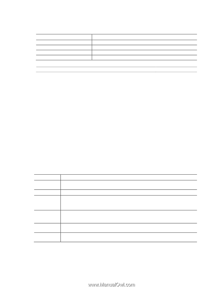
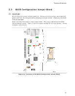
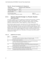
Intel Desktop Board D2550MUD2 Technical Product Specification Table 29. Thermal Considerations for Components Component Intel Atom processor Processor voltage regulator area Intel NM10 Express Chipset Memory SO-DIMM Maximum Case Temperature 100 oC 85 oC 113 oC 85 oC For information about Processor datasheets and specification updates Refer to Section 1.2, page 16 2.6.1 Passive Heatsink Design in a Passive System Environment This section highlights important guidelines and related thermal boundary conditions for passive heatsink design in a passive system environment. Passive heatsink describes a thermal solution without a fan attached. Passive system environment describes a chassis with either a power supply fan or a built-in system fan. This information should be used in conjunction with the Thermal and Mechanical Design Guide (TMDG) published for the Intel Atom processor D2000 series. The TMDG contains detailed package information and thermal mechanical specifications for the processors. The TMDG also contains information on how to enable a completely fanless design provided the right usage scenario and boundary conditions are observed for optimal thermal design. While the TMSDG has a section on thermal design for passive system environments (page 32), the information in this section can also be used to complement the TMDG. 2.6.1.1 Definition of Terms Term TA TJ ΨJA TIM TDP TA external Description The measured ambient temperature locally surrounding the processor. The ambient temperature should be measured just upstream of a passive heatsink. Processor junction temperature. Junction-to-ambient thermal characterization parameter (psi). A measure of thermal solution performance using total package power. Defined as (TJ - TA)/TDP. Note: Heat source must be specified for Ψ measurements. Thermal Interface Material: the thermally conductive compound between the heatsink and the processor die surface. This material fills the air gaps and voids, and enhances the transfer of the heat from the processor die surface to the heatsink. Thermal Design Power: a power dissipation target based on worst-case applications. Thermal solutions should be designed to dissipate the thermal design power. The measured external ambient temperature surrounding the chassis. The external ambient temperature should be measured just upstream of the chassis inlet vent. 60
-
 1
1 -
2
-
3
-
4
-
5
-
6
-
7
-
8
-
9
-
10
-
11
-
12
-
13
-
14
-
15
-
16
-
17
-
18
-
19
-
20
-
21
-
22
-
23
-
24
-
25
-
26
-
27
-
28
-
29
-
30
-
31
-
32
-
33
-
34
-
35
-
36
-
37
-
38
-
39
-
40
-
41
-
42
-
43
-
44
-
45
-
46
-
47
-
48
-
49
-
50
-
51
-
52
-
53
-
54
-
 55
55 -
 56
56 -
 57
57 -
 58
58 -
 59
59 -
 60
60 -
 61
61 -
 62
62 -
 63
63 -
 64
64 -
 65
65 -
66
-
67
-
68
-
69
-
70
-
71
-
72
-
73
-
74
-
75
-
76
-
77
-
78
-
79
-
80
-
81
-
82
-
83
-
84
-
85
-
86
-
87
-
88
-
89
-
90
-
91
-
92
-
93
-
94
-
95
-
96
 |
 |