Intel D425KT Product Guide - Page 16
LAN Subsystem, LAN Status LEDs, Table 4. LAN Status LEDs - lan driver
 |
View all Intel D425KT manuals
Add to My Manuals
Save this manual to your list of manuals |
Page 16 highlights
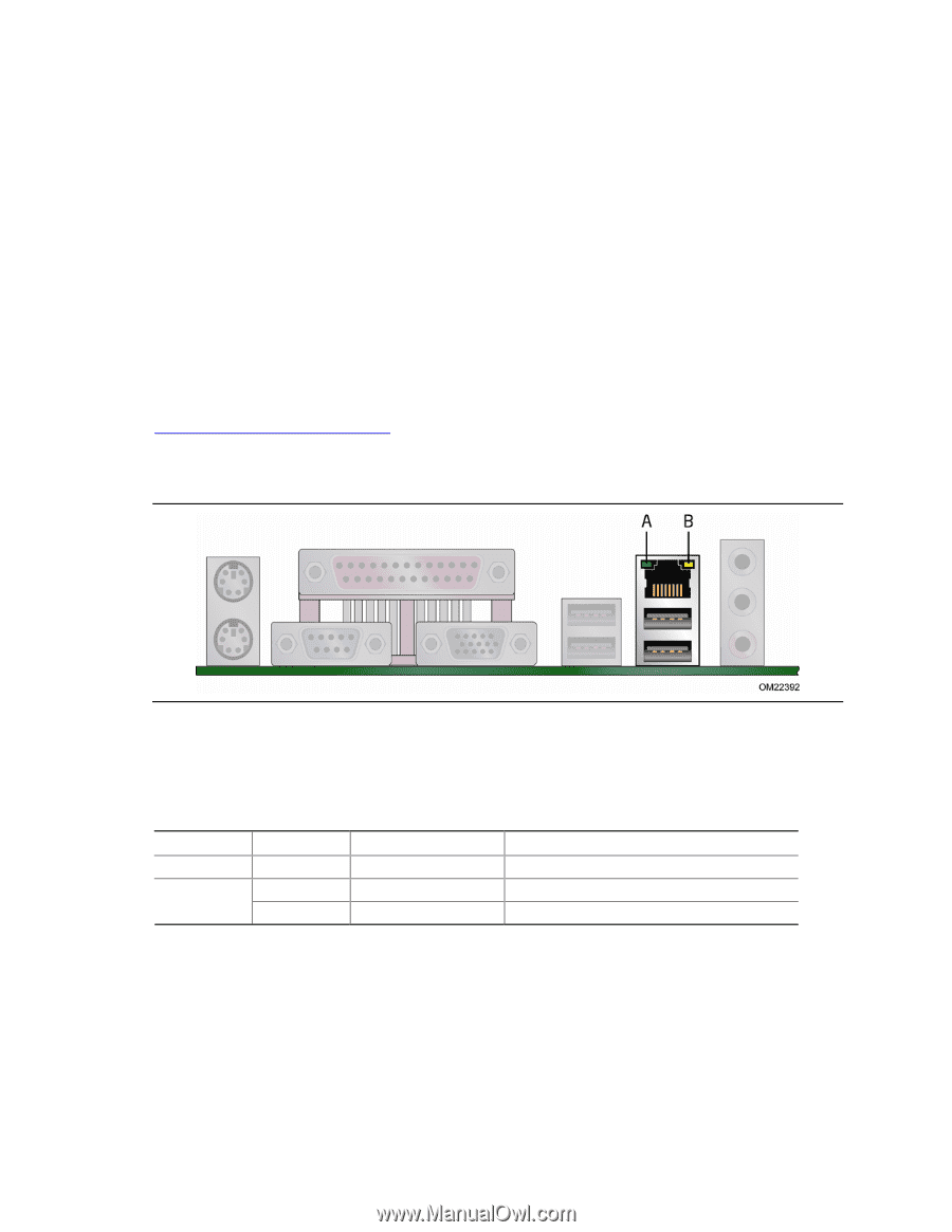
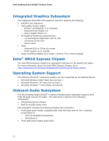
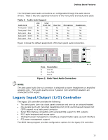
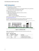
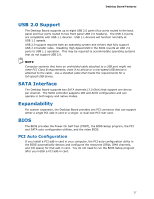
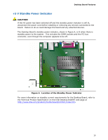
Intel Desktop Board D425KT Product Guide LAN Subsystem The LAN subsystem consists of the following: • Intel NM10 Express Chipset • Realtek 8105E Ethernet Controller for 10/100 Mbits/s Ethernet LAN connectivity • RJ-45 LAN connector with integrated status LEDs Additional features of the LAN subsystem include: • CSMA/CD protocol engine • LAN connect interface that supports the ethernet controller • PCI bus power management ⎯ Supports ACPI technology ⎯ Supports LAN wake capabilities LAN drivers are available from Intel's World Wide Web site at http://downloadcenter.intel.com/. Two LEDs are built into the RJ-45 LAN connector located on the back panel (see Figure 3). These LEDs indicate the operating states of the LAN. Figure 3. LAN Status LEDs Table 4 describes the LED states when the board is powered up and the LAN subsystem is operating. Table 4. LAN Status LEDs LED Activity (A) Speed (B) LED Color Green N/A Yellow LED State Blinking Off On Indicates LAN activity is occurring. 10 Mbits/s data rate is selected. 100 Mbits/s data rate is selected. 16
-
 1
1 -
2
-
3
-
4
-
5
-
6
-
7
-
8
-
9
-
10
-
 11
11 -
 12
12 -
 13
13 -
 14
14 -
 15
15 -
 16
16 -
 17
17 -
 18
18 -
 19
19 -
 20
20 -
 21
21 -
22
-
23
-
24
-
25
-
26
-
27
-
28
-
29
-
30
-
31
-
32
-
33
-
34
-
35
-
36
-
37
-
38
-
39
-
40
-
41
-
42
-
43
-
44
-
45
-
46
-
47
-
48
-
49
-
50
-
51
-
52
-
53
-
54
-
55
-
56
-
57
-
58
-
59
-
60
 |
 |