Intel D425KT Product Guide - Page 7

s, Tables, Intel Desktop Board D425KT China RoHS Material Self Declaration Table - memory support

Page 7 highlights

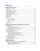
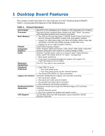
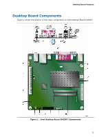
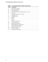
Contents Figures 1. Intel Desktop Board D425KT Components 11 2. Back Panel Audio Connectors 15 3. LAN Status LEDs 16 4. Location of the Standby Power Indicator 19 5. Installing the I/O Shield 26 6. Intel Desktop Board D425KT Mounting Screw Holes 27 7. Installing System Memory 28 8. Connecting the Serial ATA Cable 29 9. Internal Headers 30 10. Location of the Chassis Fan Header 33 11. Connecting Power Supply Cables 34 12. BIOS Configuration Jumper Block 35 13. Removing the Battery 41 14. Intel Desktop Board D425KT China RoHS Material Self Declaration Table 54 Tables 1. Feature Summary 9 2. Intel Desktop Board D425KT Components 12 3. Audio Jack Support 15 4. LAN Status LEDs 16 5. Front Panel Audio Header for Intel HD Audio 31 6. Front Panel Audio Header for AC '97 Audio 31 7. Serial Port Header (COM 1 31 8. Front Panel Header Signal Names 32 9. Front Panel USB Headers 32 10. Jumper Settings for the BIOS Setup Program Modes 36 11. AcceptableDrives/Media Types for BIOS Recovery 45 12. BIOS Beep Codes 47 13. BIOS Front-panel Power LED Blink Codes 48 14. POST Error Messages 48 15. Safety Standards 49 16. EMC Regulations 55 17. Regulatory Compliance Marks 58 18. ENERGY STAR Requirements 60 vii

  • 1
  • 2
  • 3
  • 4
  • 5
  • 6
  • 7
  • 8
  • 9
  • 10
  • 11
  • 12
  • 13
  • 14
  • 15
  • 16
  • 17
  • 18
  • 19
  • 20
  • 21
  • 22
  • 23
  • 24
  • 25
  • 26
  • 27
  • 28
  • 29
  • 30
  • 31
  • 32
  • 33
  • 34
  • 35
  • 36
  • 37
  • 38
  • 39
  • 40
  • 41
  • 42
  • 43
  • 44
  • 45
  • 46
  • 47
  • 48
  • 49
  • 50
  • 51
  • 52
  • 53
  • 54
  • 55
  • 56
  • 57
  • 58
  • 59
  • 60

Contents
vii
Figures
1. Intel Desktop Board D425KT Components
........................................................
11
2. Back Panel Audio Connectors
.........................................................................
15
3. LAN Status LEDs
..........................................................................................
16
4.
Location of the Standby Power Indicator
..........................................................
19
5. Installing the I/O Shield
................................................................................
26
6.
Intel Desktop Board D425KT Mounting Screw Holes
...........................................
27
7. Installing System Memory
.............................................................................
28
8. Connecting the Serial ATA Cable
.....................................................................
29
9. Internal Headers
..........................................................................................
30
10. Location of the Chassis Fan Header
.................................................................
33
11. Connecting Power Supply Cables
....................................................................
34
12. BIOS Configuration Jumper Block
....................................................................
35
13. Removing the Battery
...................................................................................
41
14. Intel Desktop Board D425KT China RoHS Material Self Declaration Table
..............
54
Tables
1.
Feature Summary
..........................................................................................
9
2.
Intel Desktop Board D425KT Components
........................................................
12
3.
Audio Jack Support
.......................................................................................
15
4.
LAN Status LEDs
..........................................................................................
16
5.
Front Panel Audio Header for Intel HD Audio
.....................................................
31
6.
Front Panel Audio Header for AC ‘97 Audio
.......................................................
31
7.
Serial Port Header (COM 1)
............................................................................
31
8.
Front Panel Header Signal Names
...................................................................
32
9.
Front Panel USB Headers
...............................................................................
32
10.
Jumper Settings for the BIOS Setup Program Modes
..........................................
36
11.
AcceptableDrives/Media Types for BIOS Recovery
.............................................
45
12.
BIOS Beep Codes
.........................................................................................
47
13.
BIOS Front-panel Power LED Blink Codes
.........................................................
48
14.
POST Error Messages
....................................................................................
48
15.
Safety Standards
..........................................................................................
49
16.
EMC Regulations
...........................................................................................
55
17.
Regulatory Compliance Marks
.........................................................................
58
18.
ENERGY STAR Requirements
..........................................................................
60