Intel D845EPI Intel Desktop Board D845EPI Technical Product Specification - Page 59
Thermal Considerations
 |
View all Intel D845EPI manuals
Add to My Manuals
Save this manual to your list of manuals |
Page 59 highlights
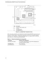
Technical Reference 2.11.4 Power Supply Considerations CAUTION The +5 V standby line for the power supply must be capable of providing adequate +5 V standby current. Failure to do so can damage the power supply. The total amount of standby current required depends on the wake devices supported and manufacturing options. System integrators should refer to the power usage values listed in Table 32 when selecting a power supply for use with the Desktop Board D845EPI. Additional power required will depend on configurations chosen by the integrator. The power supply must comply with the following recommendations found in the indicated sections of the ATX form factor specification: • The potential relation between 3.3 VDC and +5 VDC power rails (Section 4.2) • The current capability of the +5 VSB line (Section 4.2.1.2) • All timing parameters (Section 4.2.1.3) • All voltage tolerances (Section 4.2.2) For information about The ATX form factor specification Refer to Section 1.5, page 17 2.12 Thermal Considerations CAUTION Ensure that the ambient temperature does not exceed the Desktop Board's maximum operating temperature. Failure to do so could cause components to exceed their maximum case temperature and malfunction. For information about the maximum operating temperature, see the environmental specifications in Section 2.14. CAUTION Ensure that proper airflow is maintained in the processor voltage regulator circuit. Failure to do so may result in damage to the voltage regulator circuit. The processor voltage regulator area (item A in Figure 13) can reach a temperature of up to 85 oC in an open chassis. Figure 13 shows the locations of the localized high temperature zones. 59
-
 1
1 -
2
-
3
-
4
-
5
-
6
-
7
-
8
-
9
-
10
-
11
-
12
-
13
-
14
-
15
-
16
-
17
-
18
-
19
-
20
-
21
-
22
-
23
-
24
-
25
-
26
-
27
-
28
-
29
-
30
-
31
-
32
-
33
-
34
-
35
-
36
-
37
-
38
-
39
-
40
-
41
-
42
-
43
-
44
-
45
-
46
-
47
-
48
-
49
-
50
-
51
-
52
-
53
-
 54
54 -
 55
55 -
 56
56 -
 57
57 -
 58
58 -
 59
59 -
 60
60 -
 61
61 -
 62
62 -
 63
63 -
 64
64 -
65
-
66
-
67
-
68
-
69
-
70
-
71
-
72
-
73
-
74
-
75
-
76
-
77
-
78
-
79
-
80
-
81
-
82
-
83
-
84
-
85
-
86
-
87
-
88
-
89
-
90
-
91
-
92
-
93
-
94
-
95
-
96
-
97
-
98
-
99
-
100
-
101
-
102
-
103
-
104
-
105
-
106
 |
 |
