Intel D915GVWB English Product Guide - Page 41
Connecting Fan and Power Cables
 |
View all Intel D915GVWB manuals
Add to My Manuals
Save this manual to your list of manuals |
Page 41 highlights
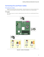
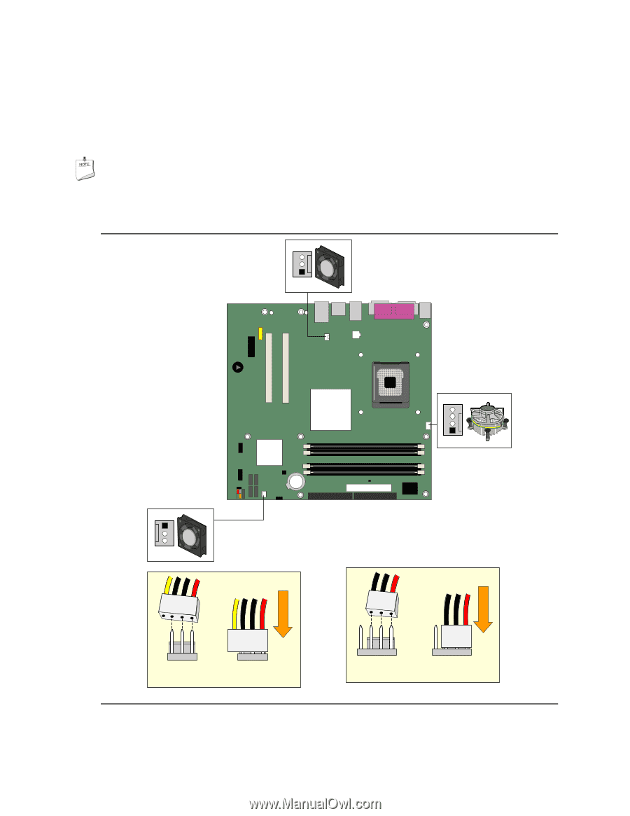
Installing and Replacing Desktop Board Components Connecting Fan and Power Cables Connecting Fan Cables Figure 20 shows the location of the fan headers. Connect the processor's fan heat sink cable to the 4-pin processor fan header on the board. Connect chassis fan cables to the 3-pin fan headers. NOTE If a 3-pin fan connector is used in a 4-pin fan header, the fan will not be controlled and will run at full speed. 3 21 A 3 21 B 43 2 1 A Figure 20. Location of Fan Headers 43 2 1 B OM17373 41
-
 1
1 -
2
-
3
-
4
-
5
-
6
-
7
-
8
-
9
-
10
-
11
-
12
-
13
-
14
-
15
-
16
-
17
-
18
-
19
-
20
-
21
-
22
-
23
-
24
-
25
-
26
-
27
-
28
-
29
-
30
-
31
-
32
-
33
-
34
-
35
-
 36
36 -
 37
37 -
 38
38 -
 39
39 -
 40
40 -
 41
41 -
 42
42 -
 43
43 -
 44
44 -
 45
45 -
 46
46 -
47
-
48
-
49
-
50
-
51
-
52
-
53
-
54
-
55
-
56
-
57
-
58
-
59
-
60
-
61
-
62
-
63
-
64
 |
 |
Installing and Replacing Desktop Board Components
41
Connecting Fan and Power Cables
Connecting Fan Cables
Figure 20 shows the location of the fan headers.
Connect the processor’s fan heat sink cable to the
4-pin processor fan header on the board.
Connect chassis fan cables to the 3-pin fan headers.
NOTE
If a 3-pin fan connector is used in a 4-pin fan header, the fan will not be controlled and will run at
full speed.
OM17373
3
1
2
4
3
1
2
4
A
B
3
1
2
3
1
2
B
A
Figure 20.
Location of Fan Headers