Contents
vii
Figures
1.
Intel Desktop Board D915GVWB Components
..............................................................
11
2.
Location of Standby Power Indicator
..............................................................................
20
3.
Installing the I/O Shield
...................................................................................................
26
4.
Mounting Screw Hole Locations
.....................................................................................
27
5.
Lift Socket Lever
.............................................................................................................
28
6.
Lift the Load Plate and Don’t Touch the Socket Contacts
..............................................
28
7.
Remove the Protective Socket Cover
.............................................................................
29
8.
Remove the Processor from the Protective Processor Cover/Do Not Touch
.................
29
9.
Install Processor
.............................................................................................................
30
10. Close the Load Plate
......................................................................................................
30
11. Connecting the Processor Fan Heat Sink Cable to the Processor Fan Connector
........
31
12. Dual Configuration Example 1
........................................................................................
32
13. Dual Configuration Example 2
........................................................................................
33
14. Dual Configuration Example 3
........................................................................................
33
15. Installing a DIMM
............................................................................................................
34
16. Connecting the IDE Cable
..............................................................................................
36
17. Connecting the Serial ATA Cable
...................................................................................
37
18. Internal Headers
.............................................................................................................
38
19. Back Panel Audio Connectors for Flexible 6-Channel Audio System
............................
40
20. Location of Fan Headers
................................................................................................
41
21. Connecting 2x10 Power Supply Cables
.........................................................................
42
22. Connecting 2x12 Power Supply Cables
.........................................................................
43
23. Location of Other Connectors
.........................................................................................
44
24. Location of the BIOS Configuration Jumper Block
.........................................................
45
25. Back Panel Connectors
..................................................................................................
47
26. Removing the Battery
.....................................................................................................
52
27. F2 Key
............................................................................................................................
53
Tables
1.
Feature Summary
.............................................................................................................
9
2.
Manufacturing Option
.....................................................................................................
10
3.
Desktop Board D915GVWB Components
......................................................................
12
4.
RJ-45 10/100 Ethernet LAN Connector LEDs
................................................................
16
5.
USB 2.0 Header Signal Names
......................................................................................
39
6.
Front Panel Header Signal Names
.................................................................................
39
7.
Front Panel Audio Header Signal Names
.......................................................................
39
8.
Jumper Settings for the BIOS Setup Program Modes
....................................................
45
9.
BIOS Beep Code
............................................................................................................
57
10.
BIOS Error Messages
.....................................................................................................
57
11.
Safety Regulations
.........................................................................................................
59
12.
EMC Regulations
............................................................................................................
61
13.
Product Certification Markings
........................................................................................
63

 1
1 2
2 3
3 4
4 5
5 6
6 7
7 8
8 9
9 10
10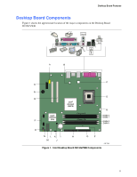 11
11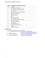 12
12

