Intel D915PGN Product Guide - Page 44
Connecting Internal Headers
 |
UPC - 735858178341
View all Intel D915PGN manuals
Add to My Manuals
Save this manual to your list of manuals |
Page 44 highlights
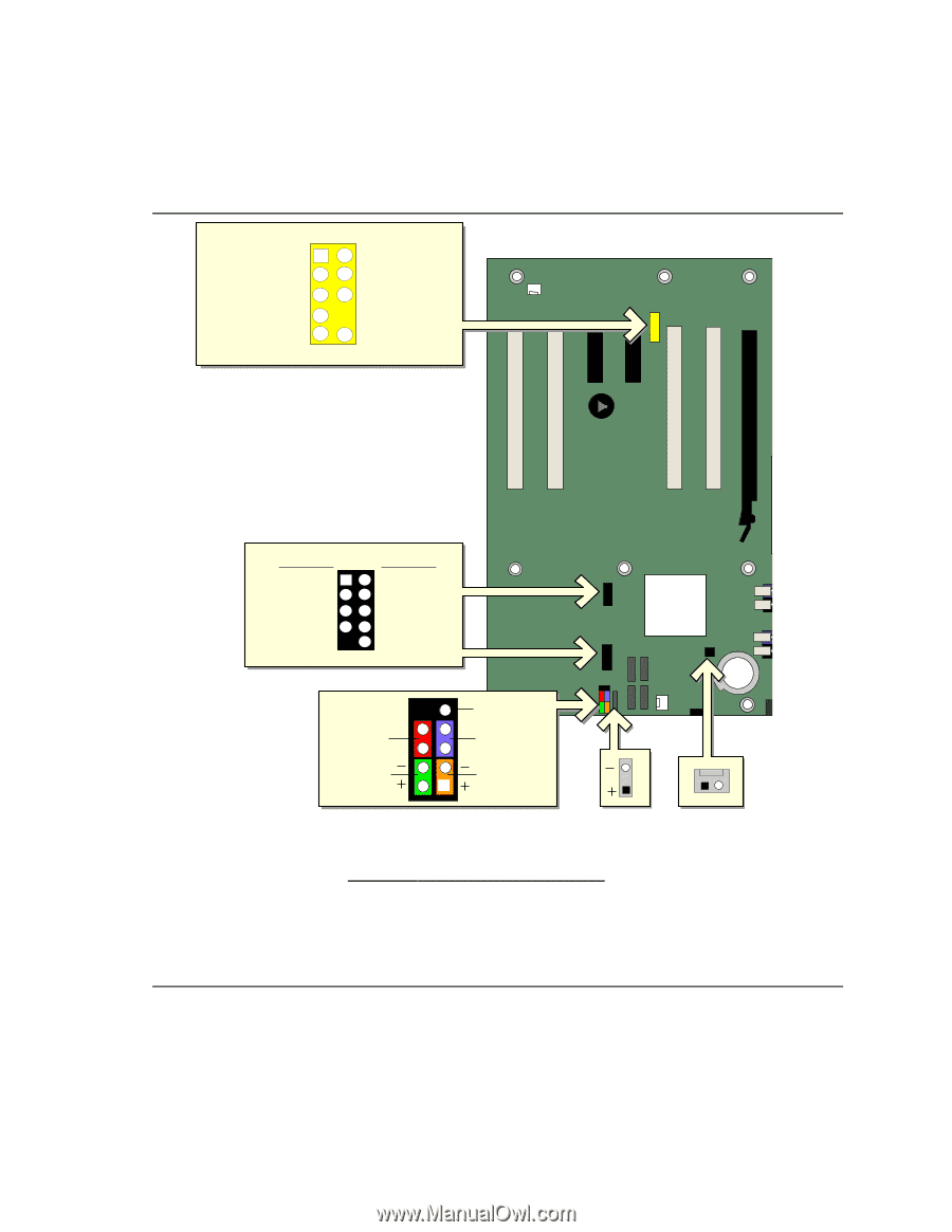
Intel Desktop Board D915PGN/D915PSY/D915PCY/D915PCM Product Guide Connecting Internal Headers Before connecting cables to the internal headers, observe the precautions in "Before You Begin" on page 27. Port1L Port1R Port2R Sense_Send Port2L 12 34 56 7 9 10 GND Presence# Sense1_Ret Key (no pin) Sense2_Ret E USB A Power (+5V) DD+ Ground Key (no pin) USB B 1 2 Power (+5V) 3 4 D5 6 D+ 7 8 Ground 10 N/C D 9 No Connection On/Off 87 65 Reset Power LED 43 HD LED 3 21 1 C B Item A B C D E Description Chassis intrusion Power LED audio Front panel USB 2.0 Front panel audio Figure 21. Internal Headers 1 A OM16890 44
-
 1
1 -
2
-
3
-
4
-
5
-
6
-
7
-
8
-
9
-
10
-
11
-
12
-
13
-
14
-
15
-
16
-
17
-
18
-
19
-
20
-
21
-
22
-
23
-
24
-
25
-
26
-
27
-
28
-
29
-
30
-
31
-
32
-
33
-
34
-
35
-
36
-
37
-
38
-
 39
39 -
 40
40 -
 41
41 -
 42
42 -
 43
43 -
 44
44 -
 45
45 -
 46
46 -
 47
47 -
 48
48 -
 49
49 -
50
-
51
-
52
-
53
-
54
-
55
-
56
-
57
-
58
-
59
-
60
-
61
-
62
-
63
-
64
-
65
-
66
-
67
-
68
-
69
-
70
-
71
-
72
 |
 |
Intel Desktop Board D915PGN/D915PSY/D915PCY/D915PCM Product Guide
44
Connecting Internal Headers
Before connecting cables to the internal headers, observe the precautions in "Before You Begin" on
page 27.
OM16890
D
B
C
1
5
6
7
3
4
2
10
9
Port1L
Port1R
Port2R
Sense_Send
Port2L
GND
Presence#
Sense1_Ret
Key (no pin)
Sense2_Ret
1
3
On/Off
Power LED
HD LED
Reset
No Connection
1
2
3
4
5
7
6
8
9
USB A
USB B
1
5
6
7
8
3
4
2
10
Power (+5V)
Power (+5V)
D-
D+
Ground
Key (no pin)
N/C
D-
D+
Ground
E
A
1
Item
Description
A
Chassis intrusion
B
Power LED audio
C
Front panel
D
USB 2.0
E
Front panel audio
Figure 21.
Internal Headers