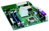
Intel D915PGN Product Guide - Page 7

Connecting the Processor Fan Heat Sink Cable to the Processor Fan Connector - bios

Page 7 highlights

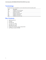
Contents B Regulatory Compliance Safety Regulations ...69 European Union Declaration of Conformity Statement 69 Product Ecology Statements 70 EMC Regulations ...71 Product Certification Markings (Board Level 72 Figures 1. Desktop Boards D915PGN and D915PCY Components 12 2. Intel Desktop Boards D915PSY and D915PCM Components 14 3. Location of Standby Power Indicator 24 4. Installing the I/O Shield 30 5. Desktop Board D915PGN and D915PCY Mounting Screw Hole Locations 31 6. Lift Socket Lever ...32 7. Lift the Load Plate and Don't Touch the Socket Contacts 32 8. Remove the Protective Cover 33 9. Remove the Processor from the Protective Cover 33 10. Install Processor ...34 11. Close the Load Plate ...34 12. Connecting the Processor Fan Heat Sink Cable to the Processor Fan Connector ........35 13. Dual Configuration Example 1 36 14. Dual Configuration Example 2 37 15. Dual Configuration Example 3 37 16. Matching the Correct DIMM 38 17. Installing a DIMM ...39 18. Removing the PCI Express x16 Card 41 19. Connecting the IDE Cable 42 20. Connecting the Serial ATA Cable 43 21. Internal Headers ...44 22. Back Panel Audio Connectors for Flexible 6-Channel Audio System 47 23. Location of Fan Headers 48 24. Connecting 2x10 Power Supply Cables 49 25. Connecting 2x12 Power Supply Cables 50 26. Location of the PCI Bus Add-in Card and Peripheral Interface Connectors for Desktop Boards D915PGN and D915PCY 51 27. Location of the BIOS Configuration Jumper Block 52 28. Back Panel Connectors 54 29. Removing the Battery 58 Tables 1. Feature Summary ...9 2. Manufacturing Option...11 3. Desktop Boards D915PGN and D915PCY Components 13 4. Desktop Boards D915PSY and D915PCM Components 15 5. Desktop Board D915PGN/D915PSY Memory Configurations 17 6. Desktop Board D915PCY/D915PCM Memory Configurations 17 7. RJ-45 10/100 Ethernet LAN Connector LEDs 20 8. Front Panel Audio Header Signal Names 45 vii

  • 1
  • 2
  • 3
  • 4
  • 5
  • 6
  • 7
  • 8
  • 9
  • 10
  • 11
  • 12
  • 13
  • 14
  • 15
  • 16
  • 17
  • 18
  • 19
  • 20
  • 21
  • 22
  • 23
  • 24
  • 25
  • 26
  • 27
  • 28
  • 29
  • 30
  • 31
  • 32
  • 33
  • 34
  • 35
  • 36
  • 37
  • 38
  • 39
  • 40
  • 41
  • 42
  • 43
  • 44
  • 45
  • 46
  • 47
  • 48
  • 49
  • 50
  • 51
  • 52
  • 53
  • 54
  • 55
  • 56
  • 57
  • 58
  • 59
  • 60
  • 61
  • 62
  • 63
  • 64
  • 65
  • 66
  • 67
  • 68
  • 69
  • 70
  • 71
  • 72

Contents
vii
B
Regulatory Compliance
Safety Regulations
..............................................................................................................
69
European Union Declaration of Conformity Statement
........................................................
69
Product Ecology Statements
...............................................................................................
70
EMC Regulations
................................................................................................................
71
Product Certification Markings (Board Level)
......................................................................
72
Figures
1.
Desktop Boards D915PGN and D915PCY Components
...............................................
12
2.
Intel Desktop Boards D915PSY and D915PCM Components
.......................................
14
3.
Location of Standby Power Indicator
.............................................................................
24
4.
Installing the I/O Shield
.................................................................................................
30
5.
Desktop Board D915PGN and D915PCY Mounting Screw Hole Locations
...................
31
6.
Lift Socket Lever
...........................................................................................................
32
7.
Lift the Load Plate and Don’t Touch the Socket Contacts
.............................................
32
8.
Remove the Protective Cover
.......................................................................................
33
9.
Remove the Processor from the Protective Cover
........................................................
33
10.
Install Processor
...........................................................................................................
34
11.
Close the Load Plate
....................................................................................................
34
12.
Connecting the Processor Fan Heat Sink Cable to the Processor Fan Connector
........
35
13.
Dual Configuration Example 1
......................................................................................
36
14.
Dual Configuration Example 2
......................................................................................
37
15.
Dual Configuration Example 3
......................................................................................
37
16.
Matching the Correct DIMM
..........................................................................................
38
17.
Installing a DIMM
..........................................................................................................
39
18.
Removing the PCI Express x16 Card
............................................................................
41
19.
Connecting the IDE Cable
............................................................................................
42
20.
Connecting the Serial ATA Cable
.................................................................................
43
21.
Internal Headers
...........................................................................................................
44
22.
Back Panel Audio Connectors for Flexible 6-Channel Audio System
............................
47
23.
Location of Fan Headers
...............................................................................................
48
24.
Connecting 2x10 Power Supply Cables
........................................................................
49
25.
Connecting 2x12 Power Supply Cables
........................................................................
50
26.
Location of the PCI Bus Add-in Card and Peripheral Interface Connectors for
Desktop Boards D915PGN and D915PCY
....................................................................
51
27.
Location of the BIOS Configuration Jumper Block
........................................................
52
28.
Back Panel Connectors
................................................................................................
54
29.
Removing the Battery
...................................................................................................
58
Tables
1.
Feature Summary
...........................................................................................................
9
2.
Manufacturing Option
....................................................................................................
11
3.
Desktop Boards D915PGN and D915PCY Components
...............................................
13
4.
Desktop Boards D915PSY and D915PCM Components
...............................................
15
5.
Desktop Board D915PGN/D915PSY Memory Configurations
.......................................
17
6.
Desktop Board D915PCY/D915PCM Memory Configurations
.......................................
17
7.
RJ-45 10/100 Ethernet LAN Connector LEDs
...............................................................
20
8.
Front Panel Audio Header Signal Names
......................................................................
45