Intel D945GSEJT Product Guide - Page 37
Internal Connectors and Headers, Table 6. Serial Port Header COM 1 and COM 2 - audio header
 |
UPC - 735858206945
View all Intel D945GSEJT manuals
Add to My Manuals
Save this manual to your list of manuals |
Page 37 highlights
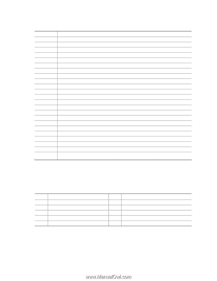
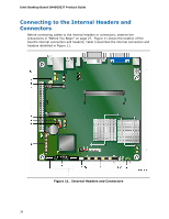
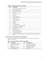
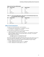
Installing and Replacing Desktop Board Components Table 5. Internal Connectors and Headers Item A B C D E F G H I J K L M N O P Q R S T U V W Description +12 V internal power connector (ATX12V) Serial port header (COM 2) Serial port header (COM 1) PS/2 keyboard port header Reserved PATA connector (44-pin) Reserved Chassis fan header Chassis intrusion header SATA connectors SATA power connector Parallel port header Reserved Reserved Front panel header Front panel wireless activity LED header PCI Express Mini Card connector PCI bus add-in card connector S/PDIF header Front panel USB header Internal mono speaker header Front panel audio header Front panel USB header with Intel Z-U130 USB Solid-State Drive (or compatible device) support Internal Connectors and Headers Table 6 through Table 21 list the signal names for the connectors and headers in Figure 11 and Table 5. Table 6. Serial Port Header (COM 1 and COM 2) Pin Signal Name Pin Signal Name 1 DCD (Data Carrier Detect) 3 TXD# (Transmit Data) 5 Ground 7 RTS (Request To Send) 9 RI (Ring Indicator) 2 RXD# (Receive Data) 4 DTR (Data Terminal Ready) 6 DSR (Data Set Ready) 8 CTS (Clear To Send) 10 Key (no pin) 37
-
 1
1 -
2
-
3
-
4
-
5
-
6
-
7
-
8
-
9
-
10
-
11
-
12
-
13
-
14
-
15
-
16
-
17
-
18
-
19
-
20
-
21
-
22
-
23
-
24
-
25
-
26
-
27
-
28
-
29
-
30
-
31
-
 32
32 -
 33
33 -
 34
34 -
 35
35 -
 36
36 -
 37
37 -
 38
38 -
 39
39 -
 40
40 -
 41
41 -
 42
42 -
43
-
44
-
45
-
46
-
47
-
48
-
49
-
50
-
51
-
52
-
53
-
54
-
55
-
56
-
57
-
58
-
59
-
60
-
61
-
62
-
63
-
64
-
65
-
66
-
67
-
68
-
69
-
70
-
71
-
72
 |
 |