Intel D945GSEJT Product Guide - Page 44
Front Panel USB Headers, Power/Sleep LED Pins, Table 22. States for a One-Color Power LED
 |
UPC - 735858206945
View all Intel D945GSEJT manuals
Add to My Manuals
Save this manual to your list of manuals |
Page 44 highlights
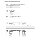
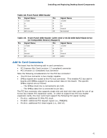
Intel Desktop Board D945GSEJT Product Guide Power/Sleep LED Pins Pins 2 and 4 can be connected to a one- or two-color LED. Table 22 shows the possible states for a one-color power LED. Table 22. States for a One-Color Power LED LED State Off Blinking Steady Green Description Power off/hibernate (S5/S4) Sleeping (S3) Running/Away (S0/S1) NOTE The LED states listed in Table 22 are default settings and can be modified through the BIOS setup. Systems built with a dual-color front panel power LED can also use alternate color state options. Power Switch Pins Pins 6 and 8 can be connected to a front panel momentary-contact power switch. The switch must pull the SW_ON# pin to ground for at least 50 ms to signal the power supply to switch on or off. (The time requirement is due to internal debounce circuitry on the board.) At least two seconds must pass before the power supply will recognize another on/off signal. Front Panel USB Headers Figure 13 is a connection diagram for the standard front panel USB header (see Figure 11, T). Figure 13. Connection Diagram for the Standard Front Panel USB Header 44
-
 1
1 -
2
-
3
-
4
-
5
-
6
-
7
-
8
-
9
-
10
-
11
-
12
-
13
-
14
-
15
-
16
-
17
-
18
-
19
-
20
-
21
-
22
-
23
-
24
-
25
-
26
-
27
-
28
-
29
-
30
-
31
-
32
-
33
-
34
-
35
-
36
-
37
-
38
-
 39
39 -
 40
40 -
 41
41 -
 42
42 -
 43
43 -
 44
44 -
 45
45 -
 46
46 -
 47
47 -
 48
48 -
 49
49 -
50
-
51
-
52
-
53
-
54
-
55
-
56
-
57
-
58
-
59
-
60
-
61
-
62
-
63
-
64
-
65
-
66
-
67
-
68
-
69
-
70
-
71
-
72
 |
 |