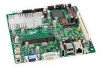
Intel D945GSEJT Product Guide - Page 7

s, Tables, Connection Diagram for the Front Panel USB Header with Intel Z-U130 USB - cables

Page 7 highlights

Contents Figures 1. Intel Desktop Board D945GSEJT Components 12 2. LAN Status LEDs 18 3. Location of the Standby Power Indicator 23 4. Installing the I/O Shield 29 5. Intel Desktop Board D945GSEJT Mounting Screw Holes 30 6. Installing System Memory 31 7. Removing System Memory 32 8. Connecting the SATA Data and Power Cables 33 9. Installing a Wireless LAN Card 34 10. Installing an Intel Z-U130 USB Solid-State Drive (or Compatible Device 35 11. Internal Headers and Connectors 36 12. Connection Diagram for Front Panel Header 43 13. Connection Diagram for the Standard Front Panel USB Header 44 14. Connection Diagram for the Front Panel USB Header with Intel Z-U130 USB Solid-State Drive (or Compatible Device) Support 45 15. Location of the Chassis Fan Header 46 16. BIOS Configuration Jumper Block 47 17. Removing the Battery 53 18. Intel Desktop Board D945GSEJT China RoHS Material Self Declaration Table .........68 Tables 1. Feature Summary 9 2. Intel Desktop Board D945GSEJT Components 13 3. LAN Status LEDs 18 4. ENERGY STAR Requirements 25 5. Internal Connectors and Headers 37 6. Serial Port Header (COM 1 and COM 2 37 7. PS/2 Keyboard Port Header 38 8. PATA Connector (44-Pin 38 9. Chassis Fan Header 38 10. Chassis Intrusion Header 39 11. SATA Power Connector 39 12. Parallel Port Header 39 13. Front Panel Wireless Activity LED Header 40 14. S/PDIF Header 40 15. Internal Mono Speaker Header 40 16. Front Panel Audio Header for Intel HD Audio 40 17. Front Panel Audio Header for AC '97 Audio 40 18. Front Panel USB Header 41 19. Front Panel USB Header (with Intel Z-U130 USB Solid-State Drive (or Compatible Device) Support 41 20. ATX12V Power Connector 42 21. Front Panel Header 43 22. States for a One-Color Power LED 44 23. Jumper Settings for the BIOS Setup Program Modes 48 24. Acceptable Drives/Media Types for BIOS Recovery 57 25. Front-panel Power LED Blink and Internal Speaker Beep Codes 59 26. POST Error Messages 60 27. Safety Standards 61 vii

  • 1
  • 2
  • 3
  • 4
  • 5
  • 6
  • 7
  • 8
  • 9
  • 10
  • 11
  • 12
  • 13
  • 14
  • 15
  • 16
  • 17
  • 18
  • 19
  • 20
  • 21
  • 22
  • 23
  • 24
  • 25
  • 26
  • 27
  • 28
  • 29
  • 30
  • 31
  • 32
  • 33
  • 34
  • 35
  • 36
  • 37
  • 38
  • 39
  • 40
  • 41
  • 42
  • 43
  • 44
  • 45
  • 46
  • 47
  • 48
  • 49
  • 50
  • 51
  • 52
  • 53
  • 54
  • 55
  • 56
  • 57
  • 58
  • 59
  • 60
  • 61
  • 62
  • 63
  • 64
  • 65
  • 66
  • 67
  • 68
  • 69
  • 70
  • 71
  • 72

Contents
vii
Figures
1. Intel Desktop Board D945GSEJT Components
...................................................
12
2. LAN Status LEDs
..........................................................................................
18
3.
Location of the Standby Power Indicator
..........................................................
23
4. Installing the I/O Shield
................................................................................
29
5.
Intel Desktop Board D945GSEJT Mounting Screw Holes
......................................
30
6. Installing System Memory
.............................................................................
31
7. Removing System Memory
.............................................................................
32
8.
Connecting the SATA Data and Power Cables
....................................................
33
9. Installing a Wireless LAN Card
........................................................................
34
10. Installing an Intel Z-U130 USB Solid-State Drive (or Compatible Device)
..............
35
11. Internal Headers and Connectors
....................................................................
36
12. Connection Diagram for Front Panel Header
.....................................................
43
13. Connection Diagram for the Standard Front Panel USB Header
............................
44
14. Connection Diagram for the Front Panel USB Header with Intel Z-U130 USB
Solid-State Drive (or Compatible Device) Support
.............................................
45
15. Location of the Chassis Fan Header
.................................................................
46
16. BIOS Configuration Jumper Block
....................................................................
47
17. Removing the Battery
...................................................................................
53
18. Intel Desktop Board D945GSEJT China RoHS Material Self Declaration Table
.........
68
Tables
1.
Feature Summary
..........................................................................................
9
2.
Intel Desktop Board D945GSEJT Components
...................................................
13
3.
LAN Status LEDs
..........................................................................................
18
4.
ENERGY STAR Requirements
..........................................................................
25
5.
Internal Connectors and Headers
....................................................................
37
6.
Serial Port Header (COM 1 and COM 2)
............................................................
37
7.
PS/2 Keyboard Port Header
............................................................................
38
8.
PATA Connector (44-Pin)
...............................................................................
38
9.
Chassis Fan Header
......................................................................................
38
10.
Chassis Intrusion Header
...............................................................................
39
11.
SATA Power Connector
..................................................................................
39
12.
Parallel Port Header
......................................................................................
39
13.
Front Panel Wireless Activity LED Header
.........................................................
40
14.
S/PDIF Header
.............................................................................................
40
15.
Internal Mono Speaker Header
.......................................................................
40
16.
Front Panel Audio Header for Intel HD Audio
.....................................................
40
17.
Front Panel Audio Header for AC ’97 Audio
.......................................................
40
18.
Front Panel USB Header
................................................................................
41
19.
Front Panel USB Header (with Intel Z-U130 USB Solid-State Drive
(or Compatible Device) Support)
....................................................................
41
20.
ATX12V Power Connector
..............................................................................
42
21.
Front Panel Header
.......................................................................................
43
22.
States for a One-Color Power LED
...................................................................
44
23.
Jumper Settings for the BIOS Setup Program Modes
..........................................
48
24.
Acceptable Drives/Media Types for BIOS Recovery
............................................
57
25.
Front-panel Power LED Blink and Internal Speaker Beep Codes
...........................
59
26.
POST Error Messages
....................................................................................
60
27.
Safety Standards
..........................................................................................
61