Intel D955XCS Product Guide
Intel D955XCS - Desktop Board Motherboard Manual
 |
UPC - 735858173841
View all Intel D955XCS manuals
Add to My Manuals
Save this manual to your list of manuals |
Intel D955XCS manual content summary:
- Intel D955XCS | Product Guide - Page 1
G Intel® Desktop Board H D955XCS Product Guide I J Order Number: C98669-002 - Intel D955XCS | Product Guide - Page 2
with the instructions, may with Intel® products. No license, express or Desktop Board D955XCS may contain design defects or errors known as errata which may cause the product to deviate from published specifications. Current characterized errata are available on request. Contact your local Intel sales - Intel D955XCS | Product Guide - Page 3
2 Installing and Replacing Desktop Board Components: instructions on how to install the desktop board and other hardware components. 3 BIOS: information about how to update the BIOS. 4 Configuring for RAID (Intel® Matrix Storage Technology) Requires Microsoft Windows* XP or 2000 and SATA Hard Drive - Intel D955XCS | Product Guide - Page 4
• Intel® Desktop Board • I/O shield • One ATA-66/100 cable • One floppy cable • Eight Serial ATA cables • Two Serial ATA power cables • One rear panel USB 2.0 adapter • One front panel USB 2.0/IEEE 1394/audio adapter • One 2x2 to 2x4 power adapter • Intel® Express Installer driver CD-ROM • Intel - Intel D955XCS | Product Guide - Page 5
Contents 1 Desktop Board Features Supported Operating Systems 10 Desktop Board Components 11 Processor ...13 Power Requirements for Intel® Pentium® Processor Extreme Edition 13 Processor Type ...13 Main Memory ...14 Intel® 955X Express Chipset 14 Audio Subsystem ...15 Input/Output (I/O) - Intel D955XCS | Product Guide - Page 6
Desktop Board D955XCS Product Guide Installing and Removing the Desktop Board 27 Installing and Removing a Processor 28 Installing a Processor 28 Installing the Processor Fan Heat Sink 31 Connecting the Processor Fan Heat Sink Cable 31 Removing the Processor 31 Installing and Removing Memory - Intel D955XCS | Product Guide - Page 7
Contacts 28 8. Remove the Protective Socket Cover 29 9. Remove the Processor from the Protective Processor Cover/Do Not Touch 29 10. Install the Processor ...30 11. Close the Load Plate ...30 12. Connecting the Processor Fan Heat Sink Cable to the Processor Fan Header 31 13. Dual Configuration - Intel D955XCS | Product Guide - Page 8
Intel Desktop Board D955XCS Product Guide Tables 1. Feature Summary...9 2. Desktop Board D955XCS Components 12 3. Power Supply Requirements Settings for the BIOS Setup Program Modes 51 11. Beep Codes...65 12. BIOS Error Messages...65 13. Safety Regulations ...67 14. Lead Free Desktop Board 71 15. - Intel D955XCS | Product Guide - Page 9
BIOS RAID BTX (12.875" x 10.50") Support for an Intel® processor in the LGA775 package with 1066/800 MHz front side bus Four 240-pin SDRAM Dual Inline Memory Module (DIMM) sockets • 667/533 MHz dual channel DDR2 SDRAM interface • Designed to support up to 8 GB of system memory Intel® 955X Express - Intel D955XCS | Product Guide - Page 10
about Intel Desktop Board D955XCS, including the Technical Product Specification (TPS), BIOS updates, and device drivers, go to: http://support.intel.com/support/motherboards/desktop/ Supported Operating Systems The desktop board supports the following operating systems: • Microsoft Windows* XP - Intel D955XCS | Product Guide - Page 11
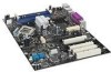
Desktop Board Features Desktop Board Components Figure 1 shows the approximate location of the major components on Desktop Board D955XCS. IEEE 1394a Line In Coaxial Line Out Optical Line Out (Toslink) A Y X W BC DE F G G R Intel 82801 (ICH7R) H Channel B DIMM 0 Channel B DIMM 1 Channel A - Intel D955XCS | Product Guide - Page 12
Board D955XCS http://www.intel.com/design/motherbd http://support.intel.com/support/motherboards/desktop • Supported processors http://support.intel.com/support/motherboards/desktop • Audio software and utilities http://www.intel.com/design/motherbd/software.htm • LAN software and drivers - Intel D955XCS | Product Guide - Page 13
to the Intel desktop board through the LGA775 socket. The supported processors list for Desktop Board D955XCS is located on the web at: http://support.intel.com/support/motherboards/desktop/ Related Links Go to the following links or pages for more information about: • Instructions on installing - Intel D955XCS | Product Guide - Page 14
about: • The latest list of tested memory, http://support.intel.com/support/motherboards/desktop/ • SDRAM specifications, http://www.intel.com/technology/memory/ • Installing memory, page 32 in Chapter 2 Intel® 955X Express Chipset The Intel 955X Express Chipset consists of the following devices - Intel D955XCS | Product Guide - Page 15
line out: • One coaxial line out • One optical (Toslink) line out Related Links Go to the following link or pages for more information about: • Audio drivers and utilities http://support.intel.com/support/motherboards/desktop/ • Installing the front panel audio solution, page 45 in Chapter 2 15 - Intel D955XCS | Product Guide - Page 16
LEDs • Configurable EEPROM that contains the MAC address LAN Subsystem Software For LAN software and drivers, refer to the D955XCS link on Intel's World Wide Web site at: http://support.intel.com/support/motherboards/desktop RJ-45 LAN Connector LEDs Two LEDs are built into the RJ-45 LAN port located - Intel D955XCS | Product Guide - Page 17
speeds. USB 2.0 support requires both an operating system and drivers that fully support USB 2.0 transfer rates. Disabling Hi-Speed USB in the BIOS processor and peripheral devices like hard disks, CD-ROM drives, and Iomega Zip* drives inside the computer. The interface supports desktop board supports - Intel D955XCS | Product Guide - Page 18
Intel Desktop Board D955XCS Product Guide Expandability The desktop board supports the following: • One PCI Express x16 add-in card • One PCI Express x4 add-in card (routed to the physical x16 connector) • One PCI Express x1 add-in card • Four PCI bus add-in cards Related Links For information about - Intel D955XCS | Product Guide - Page 19
the desktop board BIOS. Disabling the processor fan speed control will result in the fan operating at full speed if it is not a self controlled fan. It is recommended that processor fan speed control remain enabled (default BIOS setting) when using the processor fan heat-sink included with Intel - Intel D955XCS | Product Guide - Page 20
Intel Desktop Board D955XCS Product Guide used with this desktop board must be able to provide enough standby current to support the standard Instantly The desktop board's standby power indicator, shown in Figure 3, is lit when there is standby power to the system. This includes the memory modules - Intel D955XCS | Product Guide - Page 21
USB NOTE Wake from USB requires the use of a USB peripheral that supports Wake from USB. USB bus activity wakes the computer from an ACPI S1 instructions on how to replace the battery. Real-Time Clock The desktop board has a time-of-day clock and 100-year calendar. The battery on the desktop board - Intel D955XCS | Product Guide - Page 22
Intel Desktop Board D955XCS Product Guide 22 - Intel D955XCS | Product Guide - Page 23
Components This chapter tells you how to: • Install the I/O shield • Install and remove the desktop board • Install and remove a processor and memory • Install and remove a PCI Express x16 add-in card • Connect the IDE and Serial ATA cables • Connect internal headers • Install the rear and front - Intel D955XCS | Product Guide - Page 24
Intel Desktop Board D955XCS Product Guide Installation Precautions When you install and test the Intel desktop board, observe all warnings and cautions in the installation instructions. To avoid injury, be careful of: • Sharp pins on connectors • Sharp pins on printed circuit assemblies • Rough - Intel D955XCS | Product Guide - Page 25
at the front of this product guide demonstrates compliance with Canadian EMC regulations. that the calculated total current loads of all the modules within the computer is less than the output current is insufficient space on this desktop board to provide instructions for replacing and disposing of - Intel D955XCS | Product Guide - Page 26
Intel Desktop Board D955XCS Product Guide Installing the I/O Shield The desktop board comes with an I/O shield. When installed promotes correct airflow within the chassis. Install the I/O shield before installing the desktop board in the chassis. Place the shield inside the chassis as shown in Figure - Intel D955XCS | Product Guide - Page 27
. NOTE Refer to Appendix B for regulatory requirements. Refer to your chassis manual for instructions on installing and removing the desktop board. Figure 5 shows the location of the 10 mounting screw holes for Desktop Board D955XCS. G H I J Figure 5. Location of Mounting Screw Holes OM17780 27 - Intel D955XCS | Product Guide - Page 28
Intel Desktop Board D955XCS Product Guide Installing and Removing a Processor Instructions on how to install the processor to the desktop board are given below. Installing a Processor CAUTION Before installing or removing the processor, make sure that AC power has been removed by unplugging the - Intel D955XCS | Product Guide - Page 29
and Replacing Desktop Board Components 4. Remove the protective socket cover from the load plate. Do not discard the protective socket cover. Always replace the socket cover if the processor is removed from the socket (see Figure 8, E). E OM17228 Figure 8. Remove the Protective Socket Cover - Intel D955XCS | Product Guide - Page 30
Intel Desktop Board D955XCS Product Guide 6. Hold the processor with your thumb and index fingers oriented as shown in Figure 10. Make sure fingers align to the socket cutouts (see Figure 10, F). Align notches (see Figure 10, G) with the socket see (Figure 10, H). Lower the processor straight down - Intel D955XCS | Product Guide - Page 31
Fan Heat Sink Desktop Board D955XCS has an integrated processor fan heat sink retention mechanism (RM). For instructions on how to attach the processor fan heat sink to the integrated processor fan heat sink RM, refer to the boxed processor manual or the Intel World Wide Web site at: http://support - Intel D955XCS | Product Guide - Page 32
applicable Intel SDRAM memory specifications, the board requires DIMMs that support the Serial Presence Detect (SPD) data structure. You can access the PC Serial Presence Detect Specification at: http://www.intel.com/technology/memory/ddr/specs/dda18c32_64_128x72ag_a.pdf Desktop Board D955XCS has - Intel D955XCS | Product Guide - Page 33
Desktop Board Components Three DIMMs Install a matched pair of DIMMs equal in speed and size in DIMM 0 (blue) and DIMM 1 (black) of channel A. Install a DIMM equal in speed 15. Dual Configuration Example 3 NOTE All other memory configurations will result in single channel memory operation. 33 - Intel D955XCS | Product Guide - Page 34
Intel Desktop Board D955XCS Product Guide Installing DIMMs To make sure you have the correct DIMM, place the DIMM on the illustration in Figure 16 showing the DDR2 DIMM. All the notches should match with the DDR2 DIMM. DDR DDR2 mm 1 2 3 4 5 6 7 8 9 10 11 12 13 OM16943 Figure 16. Use DDR2 DIMMs 34 - Intel D955XCS | Product Guide - Page 35
Desktop Board Components To install DIMMs, follow these steps: 1. Observe the precautions in "Before You Begin" on page 23. 2. Turn off all peripheral devices connected to the computer. Turn off the computer and disconnect the AC power cord. 3. Remove the computer's cover and locate the DIMM sockets - Intel D955XCS | Product Guide - Page 36
Intel Desktop Board D955XCS Product Guide Removing DIMMs To remove a memory module, follow these steps: 1. Observe the precautions in "Before You Begin" on page 23. 2. Turn off all peripheral devices connected to the computer. Turn off the - Intel D955XCS | Product Guide - Page 37
may be damaged. The desktop board has an integrated PCI Express x16 card retention mechanism (RM). Installing a PCI Express x16 Card Use the PCI Express x16 slot indicated in Figure 18 if you are using only one video card. Follow these instructions to install a PCI Express x16 card: 1. Observe the - Intel D955XCS | Product Guide - Page 38
Intel Desktop Board D955XCS Product Guide Removing the PCI Express x16 Card Follow these instructions to remove the PCI Express x16 card from the RM: 1. Observe the precautions in "Before You Begin" the card straight up (Figure 19, C). A C B OM17798 Figure 19. Removing the PCI Express x16 Card 38 - Intel D955XCS | Product Guide - Page 39
The IDE cable can connect two drives to the desktop board. The cable supports the ATA-66/100 transfer protocol. Figure 20 Begin" on page 23. 2. Attach the cable end with the single connector to the desktop board (Figure 20). 3. Attach the cable end with the two closely spaced connectors to the - Intel D955XCS | Product Guide - Page 40
Intel Desktop Board D955XCS Product Guide Connecting the Serial ATA Cable The SATA cable (4-conductor) supports the Serial ATA protocol and connects a single drive to the desktop board. For correct cable function: 1. Observe the precaution in "Before You Begin" on page 23. 2. Attach the locking - Intel D955XCS | Product Guide - Page 41
Installing and Replacing Desktop Board Components Connecting Internal Headers Before connecting cables to the internal headers, observe the Item A B C D E F Description Front panel audio IEEE 1394a Alternate power LED IEEE 1394b Front panel Hi-speed USB Figure 22. Internal Headers OM17786 41 - Intel D955XCS | Product Guide - Page 42
Intel Desktop Board D955XCS Product Guide Front Panel Audio Header Figure 22, A on page 41 shows the location of the yellow front panel audio header. Table 5 shows the pin assignments for - Intel D955XCS | Product Guide - Page 43
Installing and Replacing Desktop Board Components USB 2.0 Headers See Figure 22, F for the location of the black USB 2.0 headers. Table 8 shows the pin assignments for the headers. Table 8. USB 2.0 Header - Intel D955XCS | Product Guide - Page 44
Intel Desktop Board D955XCS Product Guide Installing the Rear Panel Hi-Speed USB 2.0 Adapter Follow these instructions to install the rear panel USB 2.0 adapter (see Figure 23): 1. Observe the precautions in "Before You Begin" on page 23. 2. Attach the cable end with - Intel D955XCS | Product Guide - Page 45
2.0 header (black), IEEE 1394a header (blue), and IEEE 1394b header (pink) on the desktop board. 5. Install a correctly keyed and shielded cable. 6. Connect the cables to their respective headers on the desktop board. 7. Replace the cover. OM17788 Figure 24. Connecting the Front Panel USB/IEEE 1394 - Intel D955XCS | Product Guide - Page 46
A Intel Desktop Board D955XCS Product Guide Connecting Fans Connecting Fans and Chassis Intrusion See Figure 25 for fan and chassis intrusion header locations. Connect the processor's fan heat sink cable to the 4-pin processor fan header on the board. Connect chassis fan cables to the board fan - Intel D955XCS | Product Guide - Page 47
and Replacing Desktop Board Components Connecting the Auxiliary Power Output Connector NOTE Do not use a Y-adapter, power splitter, or SATA power adapter H I J Figure 26. Auxiliary Power Output Connector OM17790 The D955XCS board includes a male 1x4 power connector that can be used to provide - Intel D955XCS | Product Guide - Page 48
Intel Desktop Board D955XCS Product Guide Connecting Power Cables NOTE Failure to use the appropriate power supply and/or not connecting the 12 V (2x4) power connector to the desktop board may result in damage to the board or the system may not function properly. See Table 3 on page 13 for power - Intel D955XCS | Product Guide - Page 49
Installing and Replacing Desktop Board Components Connecting 2x12 Power Supply Cables If you have a 2x12 power supply, follow the instructions below. Figure 28 shows the location of the power connectors for a 2x12 power supply. G H 1 2 I OR J Figure 28. Connecting 2x12 Power Supply Cables - Intel D955XCS | Product Guide - Page 50
Intel Desktop Board D955XCS Product Guide Other Connectors Figure 29 shows the location of the other connectors. A B C DEF G H I J G Item Description A PCI Express x1 connector B PCI bus add-in card connector 1 C PCI Express x4 connector (routed to a physical x16 connector) D PCI bus add-in - Intel D955XCS | Product Guide - Page 51
operation. The location of the desktop board's BIOS configuration jumper is shown in Figure 30. 1 I 3 J OM17794 Figure 30. Location of the BIOS Configuration Jumper Block The three-pin BIOS configuration jumper block enables all board configurations to be done in BIOS Setup. Table 10 shows the - Intel D955XCS | Product Guide - Page 52
Intel Desktop Board D955XCS Product Guide Clearing Passwords This procedure assumes that the board is installed in the computer and the configuration jumper block is set to normal mode. 1. Observe the precautions in "Before You Begin" on page 23. 2. - Intel D955XCS | Product Guide - Page 53
Installing and Replacing Desktop Board Components Back Panel Connectors NOTE The line out connector, located on the back panel, is designed to power either headphones or amplified speakers only. Poor - Intel D955XCS | Product Guide - Page 54
Intel Desktop Board D955XCS Product Guide Replacing the Battery A coin-cell battery (CR2032) powers the real-time clock and CMOS memory. When the computer is not plugged into a wall socket, the battery has an estimated life of three years. When the computer is plugged in, the standby current from - Intel D955XCS | Product Guide - Page 55
Installing and Replacing Desktop Board Components AVVERTIMENTO Esiste il pericolo di un esplosione se la pila non viene sostituita in modo corretto. Utilizzare solo pile uguali o di tipo equivalente a quelle - Intel D955XCS | Product Guide - Page 56
Intel Desktop Board D955XCS Product Guide AWAS Risiko letupan wujud jika bateri digantikan dengan jenis yang tidak betul. Bateri sepatutnya dikitar semula jika boleh. Pelupusan bateri terpakai mestilah mematuhi peraturan alam - Intel D955XCS | Product Guide - Page 57
Installing and Replacing Desktop Board Components UYARI Yanlış türde pil takıldığında patlama riski source (wall outlet or power adapter). 3. Remove the computer cover. 4. Locate the battery on the board (see Figure 32). 5. With a medium flat-bladed screwdriver, gently pry the battery free from its - Intel D955XCS | Product Guide - Page 58
Intel Desktop Board D955XCS Product Guide 58 - Intel D955XCS | Product Guide - Page 59
of the Intel® Flash Memory Update Utility and the ease-of use of Windows-based installation wizards. To update the BIOS with the Intel Express BIOS Update utility: 1. Go to the Intel World Wide Web site: http://support.intel.com/support/motherboards/desktop/ 2. Navigate to the D955XCS page, click - Intel D955XCS | Product Guide - Page 60
: http://support.intel.com/support/motherboards/desktop Navigate to the D955XCS page, click "[view] Latest BIOS updates," and select the Iflash BIOS Update utility file. NOTE Review the instructions distributed with the update utility before attempting a BIOS update. The Iflash Memory Update utility - Intel D955XCS | Product Guide - Page 61
BIOS if an update fails. The following procedure uses recovery mode for the Setup program. See page 51 for more information on Setup modes. NOTE Because of the small amount of code available in the boot block area, there is no video support successful recovery of the BIOS core. Drive A activity will - Intel D955XCS | Product Guide - Page 62
Intel Desktop Board D955XCS Product Guide 62 - Intel D955XCS | Product Guide - Page 63
the Windows installation and install all necessary drivers. 4. Install the Intel Matrix Storage Console software via the Intel Express Installer CD included with your desktop board or after downloading it from the Internet at http://support.intel.com/support/motherboards/desktop/. The Intel Matrix - Intel D955XCS | Product Guide - Page 64
Intel Desktop Board D955XCS Product Guide Setting Up a "RAID Ready" System The Intel Matrix Storage Technology Console software offers the flexibility to upgrade from a single Serial ATA drive to RAID without reinstalling the operating system, when a second SATA hard drive is added to the system. - Intel D955XCS | Product Guide - Page 65
external ROM module does not properly checksum to zero. Table 11. Beep Codes Beep 3 Siren Description No memory CPU overheat (on reboot) BIOS Error Messages When a recoverable error occurs during the POST, the BIOS displays an error message describing the problem. Table 12. BIOS Error Messages - Intel D955XCS | Product Guide - Page 66
Intel Desktop Board D955XCS Product Guide 66 - Intel D955XCS | Product Guide - Page 67
- Safety - Part 1: General Requirements (International) European Union Declaration of Conformity Statement We, Intel Corporation, declare under our sole responsibility that the product Intel® Desktop Board D955XCS is in conformity with all applicable essential requirements necessary for CE marking - Intel D955XCS | Product Guide - Page 68
Intel Desktop Board D955XCS Product Guide Čeština Tento výrobek odpovídá požadavkům evropských směrnic 89/336/EEC a 73/23/EEC. Dansk Dette produkt er i overensstemmelse med det europæiske - Intel D955XCS | Product Guide - Page 69
the scope of covered products, available locations, shipping instructions, terms and conditions, etc. Intel Product Recycling Program http://www.intel.com/intel/other/ehs/product_ecology/Recycling_Program.htm Deutsch Als Teil von Intels Engagement für den Umweltschutz hat das Unternehmen das - Intel D955XCS | Product Guide - Page 70
Intel Desktop Board D955XCS Product Guide Français Dans le cadre de son engagement pour la protection de l'environnement, Intel a mis en œuvre le programme Intel Product Recycling Program (Programme de recyclage des produits Intel) pour permettre aux consommateurs de produits Intel de recycler les - Intel D955XCS | Product Guide - Page 71
http://www.intel.com/intel/other/ehs/product_ecology/Recycling_Program.htm web sayfasına gidin. Lead Free Desktop Board The desktop board is lead free Free Desktop Board Description Lead-Free: The symbol is used to identify electrical and electronic assemblies and components in which the lead (Pb) - Intel D955XCS | Product Guide - Page 72
Intel Desktop Board D955XCS Product Guide EMC Regulations Desktop Board D955XCS complies with the EMC regulations stated in may cause radio interference. Install and use the equipment according to the instruction manual. Korean Class B statement translation: This is household equipment that is - Intel D955XCS | Product Guide - Page 73
mark. For information about MIC certification, go to http://support.intel.com/support/motherboards/desktop/ Taiwan BSMI (Bureau of Standards, Metrology and Inspections) mark. Includes adjacent Intel company number, D33025. Printed wiring board manufacturer's recognition mark. Consists of a unique UL - Intel D955XCS | Product Guide - Page 74
Intel Desktop Board D955XCS Product Guide 74
-
 1
1 -
 2
2 -
 3
3 -
 4
4 -
 5
5 -
 6
6 -
 7
7 -
8
-
9
-
10
-
11
-
12
-
13
-
14
-
15
-
16
-
17
-
18
-
19
-
20
-
21
-
22
-
23
-
24
-
25
-
26
-
27
-
28
-
29
-
30
-
31
-
32
-
33
-
34
-
35
-
36
-
37
-
38
-
39
-
40
-
41
-
42
-
43
-
44
-
45
-
46
-
47
-
48
-
49
-
50
-
51
-
52
-
53
-
54
-
55
-
56
-
57
-
58
-
59
-
60
-
61
-
62
-
63
-
64
-
65
-
66
-
67
-
68
-
69
-
70
-
71
-
72
-
73
-
74
 |
 |

Intel
®
Desktop Board
D955XCS Product Guide
I
Order Number:
C98669-002