Contents
vii
A
Error Messages and Indicators
BIOS Beep Codes
.................................................................................................................
65
BIOS Error Messages
...........................................................................................................
65
B
Regulatory Compliance
Safety Regulations
................................................................................................................
67
European Union Declaration of Conformity Statement
.........................................................
67
Product Ecology Statements
.................................................................................................
69
EMC Regulations
..................................................................................................................
72
Product Certification Markings (Board Level)
........................................................................
73
Figures
1.
Desktop Board D955XCS Components
.........................................................................
11
2.
Back Panel LAN Port LED Locations
.............................................................................
16
3.
Location of the Standby Power Indicator
........................................................................
20
4.
Installing the I/O Shield
...................................................................................................
26
5.
Location of Mounting Screw Holes
.................................................................................
27
6.
Lift Socket Lever
.............................................................................................................
28
7.
Lift the Load Plate and Don’t Touch the Socket Contacts
..............................................
28
8.
Remove the Protective Socket Cover
.............................................................................
29
9.
Remove the Processor from the Protective Processor Cover/Do Not Touch
.................
29
10. Install the Processor
.......................................................................................................
30
11. Close the Load Plate
......................................................................................................
30
12. Connecting the Processor Fan Heat Sink Cable to the Processor Fan Header
.............
31
13. Dual Configuration Example 1
........................................................................................
32
14. Dual Configuration Example 2
........................................................................................
32
15. Dual Configuration Example 3
........................................................................................
33
16. Use DDR2 DIMMs
..........................................................................................................
34
17. Installing a DIMM
............................................................................................................
35
18. Slot to Use for One Video Card
......................................................................................
37
19. Removing the PCI Express x16 Card
.............................................................................
38
20. Connecting the IDE Cable
..............................................................................................
39
21. Connecting Serial ATA Cables
.......................................................................................
40
22. Internal Headers
.............................................................................................................
41
23. Connecting the Rear Panel Hi-Speed USB 2.0 Adapter
................................................
44
24. Connecting the Front Panel USB/IEEE 1394/Audio Cables
...........................................
45
25. Location of Fan and Chassis Intrusion Headers
.............................................................
46
26. Auxiliary Power Output Connector
.................................................................................
47
27. Connecting 2x10 Power Supply Cables
.........................................................................
48
28. Connecting 2x12 Power Supply Cables
.........................................................................
49
29. Other Connector Locations
.............................................................................................
50
30. Location of the BIOS Configuration Jumper Block
.........................................................
51
31. Back Panel Connectors
..................................................................................................
53
32. Removing the Battery
.....................................................................................................
57
33. F2 Key
............................................................................................................................
59
 1
1 2
2 3
3 4
4 5
5 6
6 7
7 8
8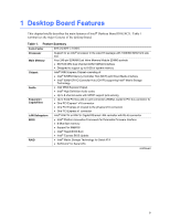 9
9 10
10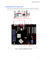 11
11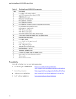 12
12