Intel DB75EN Technical Product Specification - Page 10

Front Panel Audio Header for Intel HD Audio - 2 beeps

Page 10 highlights

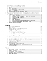
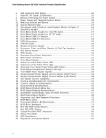
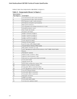
Intel Desktop Board DB75EN Technical Product Specification 6. LAN Connector LED States 28 7. Intel ME "M" State LED Behavior 33 8. Effects of Pressing the Power Switch 34 9. Power States and Targeted System Power 35 10. Wake-up Devices and Events 36 11. System Memory Map 43 12. Component-side Connectors and Headers Shown in Figure 11 46 13. Serial Port Header 47 14. Front Panel Audio Header for Intel HD Audio 47 15. Front Panel Audio Header for AC '97 Audio 47 16. Front Panel USB 2.0 Headers 47 17. Front Panel USB 3.0 Connector 48 18. SATA Connectors 48 19. S/PDIF Header 48 20. Chassis Intrusion Header 49 21. Processor, Front, and Rear Chassis (4-Pin) Fan Headers 49 22. LPC Debug Header 49 23. TPM Header 49 24. Processor Core Power Connector 51 25. Main Power Connector 51 26. Front Panel Header 52 27. States for a One-Color Power LED 53 28. States for a Two-Color Power LED 53 29. Alternate Front Panel Power/Sleep LED Header 53 30. BIOS Setup Configuration Jumper Settings 55 31. Intel MEBX Reset Header Signals 56 32. Recommended Power Supply Current Values (High Power 58 33. Recommended Power Supply Current Values (Low Power 58 34. Fan Header Current Capability 59 35. Thermal Considerations for Components 61 36. Tcontrol Values for Components 61 37. Environmental Specifications 62 38. BIOS Setup Program Menu Bar 64 39. BIOS Setup Program Function Keys 64 40. Acceptable Drives/Media Types for BIOS Recovery 67 41. Boot Device Menu Options 68 42. Supervisor and User Password Functions 70 43. BIOS Beep Codes 73 44. Front-panel Power LED Blink Codes 74 45. BIOS Error Messages 74 46. Port 80h POST Code Ranges 75 47. Port 80h POST Codes 76 48. Typical Port 80h POST Sequence 80 49. Safety Standards 81 50. EMC Regulations 87 51. Regulatory Compliance Marks 90 x

  • 1
  • 2
  • 3
  • 4
  • 5
  • 6
  • 7
  • 8
  • 9
  • 10
  • 11
  • 12
  • 13
  • 14
  • 15
  • 16
  • 17
  • 18
  • 19
  • 20
  • 21
  • 22
  • 23
  • 24
  • 25
  • 26
  • 27
  • 28
  • 29
  • 30
  • 31
  • 32
  • 33
  • 34
  • 35
  • 36
  • 37
  • 38
  • 39
  • 40
  • 41
  • 42
  • 43
  • 44
  • 45
  • 46
  • 47
  • 48
  • 49
  • 50
  • 51
  • 52
  • 53
  • 54
  • 55
  • 56
  • 57
  • 58
  • 59
  • 60
  • 61
  • 62
  • 63
  • 64
  • 65
  • 66
  • 67
  • 68
  • 69
  • 70
  • 71
  • 72
  • 73
  • 74
  • 75
  • 76
  • 77
  • 78
  • 79
  • 80
  • 81
  • 82
  • 83
  • 84
  • 85
  • 86
  • 87
  • 88
  • 89
  • 90
  • 91
  • 92
  • 93
  • 94
  • 95
  • 96

Intel Desktop Board DB75EN Technical Product Specification
x
6.
LAN Connector LED States
.................................................................
28
7.
Intel ME “M” State LED Behavior
........................................................
33
8.
Effects of Pressing the Power Switch
...................................................
34
9.
Power States and Targeted System Power
...........................................
35
10. Wake-up Devices and Events
.............................................................
36
11. System Memory Map
.........................................................................
43
12. Component-side Connectors and Headers Shown in Figure 11
................
46
13. Serial Port Header
............................................................................
47
14. Front Panel Audio Header for Intel HD Audio
........................................
47
15. Front Panel Audio Header for AC ’97 Audio
...........................................
47
16. Front Panel USB 2.0 Headers
.............................................................
47
17. Front Panel USB 3.0 Connector
...........................................................
48
18. SATA Connectors
..............................................................................
48
19. S/PDIF Header
.................................................................................
48
20. Chassis Intrusion Header
...................................................................
49
21. Processor, Front, and Rear Chassis
(4-Pin) Fan Headers
.......................
49
22. LPC Debug Header
............................................................................
49
23. TPM Header
.....................................................................................
49
24. Processor Core Power Connector
........................................................
51
25. Main Power Connector
.......................................................................
51
26. Front Panel Header
...........................................................................
52
27. States for a One-Color Power LED
.......................................................
53
28. States for a Two-Color Power LED
.......................................................
53
29. Alternate Front Panel Power/Sleep LED Header
.....................................
53
30. BIOS Setup Configuration Jumper Settings
..........................................
55
31. Intel MEBX Reset Header Signals
........................................................
56
32. Recommended Power Supply Current Values (High Power)
....................
58
33. Recommended Power Supply Current Values (Low Power)
.....................
58
34. Fan Header Current Capability
............................................................
59
35. Thermal Considerations for Components
..............................................
61
36. Tcontrol Values for Components
.........................................................
61
37. Environmental Specifications
..............................................................
62
38. BIOS Setup Program Menu Bar
...........................................................
64
39. BIOS Setup Program Function Keys
....................................................
64
40. Acceptable Drives/Media Types for BIOS Recovery
................................
67
41. Boot Device Menu Options
.................................................................
68
42. Supervisor and User Password Functions
.............................................
70
43. BIOS Beep Codes
.............................................................................
73
44. Front-panel Power LED Blink Codes
.....................................................
74
45. BIOS Error Messages
........................................................................
74
46. Port 80h POST Code Ranges
..............................................................
75
47. Port 80h POST Codes
........................................................................
76
48. Typical Port 80h POST Sequence
........................................................
80
49. Safety Standards
..............................................................................
81
50. EMC Regulations
...............................................................................
87
51. Regulatory Compliance Marks
............................................................
90