Intel DB75EN Technical Product Specification - Page 9

Error Messages and Beep Codes, Regulatory Compliance and Battery Disposal Information, s, - audio connector

Page 9 highlights

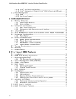
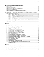
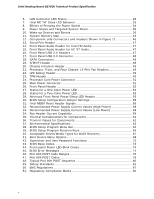
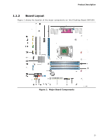
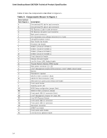
Contents 4 Error Messages and Beep Codes 4.1 Speaker 73 4.2 BIOS Beep Codes 73 4.3 Front-panel Power LED Blink Codes 74 4.4 BIOS Error Messages 74 4.5 Port 80h Power On Self Test (POST) Codes 75 5 Regulatory Compliance and Battery Disposal Information 5.1 Regulatory Compliance 81 5.1.1 Safety Standards 81 5.1.2 European Union Declaration of Conformity Statement 82 5.1.3 Product Ecology Statements 83 5.1.4 China RoHS 86 5.1.5 EMC Regulations 87 5.1.6 ENERGY STAR* 5.0, e-Standby, and ErP Compliance 89 5.1.7 Regulatory Compliance Marks (Board Level 90 5.2 Battery Disposal Information 91 Figures 1. Major Board Components 13 2. Block Diagram 15 3. Memory Channel and DIMM Configuration 21 4. Back Panel Audio Connectors 26 5. LAN Connector LED Locations 28 6. Thermal Sensors and Fan Headers 30 7. Location of the Intel ME "M" State LED 33 8. Location of the Standby Power LED 40 9. Detailed System Memory Address Map 42 10. Back Panel Connectors 44 11. Component-side Connectors and Headers 45 12. Connection Diagram for Front Panel Header 52 13. Connection Diagram for Front Panel USB 2.0 Headers 54 14. Location of the Jumper Block 55 15. Intel MEBX Reset Header 56 16. Board Dimensions 57 17. Localized High Temperature Zones 60 18. Intel Desktop Board DB75EN China RoHS Material Self Declaration Table 86 Tables 1. Specification Changes or Clarifications iii 2. Feature Summary 11 3. Components Shown in Figure 1 14 4. Supported Memory Configurations 19 5. Audio Jack Support 25 ix

  • 1
  • 2
  • 3
  • 4
  • 5
  • 6
  • 7
  • 8
  • 9
  • 10
  • 11
  • 12
  • 13
  • 14
  • 15
  • 16
  • 17
  • 18
  • 19
  • 20
  • 21
  • 22
  • 23
  • 24
  • 25
  • 26
  • 27
  • 28
  • 29
  • 30
  • 31
  • 32
  • 33
  • 34
  • 35
  • 36
  • 37
  • 38
  • 39
  • 40
  • 41
  • 42
  • 43
  • 44
  • 45
  • 46
  • 47
  • 48
  • 49
  • 50
  • 51
  • 52
  • 53
  • 54
  • 55
  • 56
  • 57
  • 58
  • 59
  • 60
  • 61
  • 62
  • 63
  • 64
  • 65
  • 66
  • 67
  • 68
  • 69
  • 70
  • 71
  • 72
  • 73
  • 74
  • 75
  • 76
  • 77
  • 78
  • 79
  • 80
  • 81
  • 82
  • 83
  • 84
  • 85
  • 86
  • 87
  • 88
  • 89
  • 90
  • 91
  • 92
  • 93
  • 94
  • 95
  • 96

Contents
ix
4
Error Messages and Beep Codes
4.1
Speaker
..........................................................................................
73
4.2
BIOS Beep Codes
.............................................................................
73
4.3
Front-panel Power LED Blink Codes
.....................................................
74
4.4
BIOS Error Messages
........................................................................
74
4.5
Port 80h Power On Self Test (POST) Codes
..........................................
75
5
Regulatory Compliance and Battery Disposal Information
5.1
Regulatory Compliance
......................................................................
81
5.1.1
Safety Standards
...................................................................
81
5.1.2
European Union Declaration of Conformity Statement
................
82
5.1.3
Product Ecology Statements
...................................................
83
5.1.4
China RoHS
..........................................................................
86
5.1.5
EMC Regulations
...................................................................
87
5.1.6
ENERGY STAR* 5.0, e-Standby, and ErP Compliance
.................
89
5.1.7
Regulatory Compliance Marks (Board Level)
.............................
90
5.2
Battery Disposal Information
..............................................................
91
Figures
1.
Major Board Components
..................................................................
13
2.
Block Diagram
..................................................................................
15
3.
Memory Channel and DIMM Configuration
............................................
21
4.
Back Panel Audio Connectors
.............................................................
26
5.
LAN Connector LED Locations
.............................................................
28
6.
Thermal Sensors and Fan Headers
......................................................
30
7.
Location of the Intel ME “M” State LED
................................................
33
8.
Location of the Standby Power LED
.....................................................
40
9.
Detailed System Memory Address Map
................................................
42
10. Back Panel Connectors
......................................................................
44
11. Component-side Connectors and Headers
............................................
45
12. Connection Diagram for Front Panel Header
.........................................
52
13. Connection Diagram for Front Panel USB 2.0 Headers
...........................
54
14. Location of the Jumper Block
.............................................................
55
15. Intel MEBX Reset Header
...................................................................
56
16. Board Dimensions
.............................................................................
57
17. Localized High Temperature Zones
.....................................................
60
18. Intel Desktop Board DB75EN China RoHS Material Self
Declaration Table
..............................................................................
86
Tables
1.
Specification Changes or Clarifications
...................................................
iii
2.
Feature Summary
.............................................................................
11
3.
Components Shown in Figure 1
..........................................................
14
4.
Supported Memory Configurations
......................................................
19
5.
Audio Jack Support
...........................................................................
25