Intel DG965RY Product Specification - Page 26
Serial ATA Interfaces - windows 7 drivers
 |
View all Intel DG965RY manuals
Add to My Manuals
Save this manual to your list of manuals |
Page 26 highlights
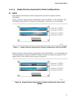
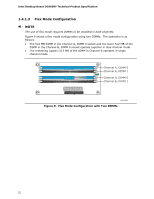
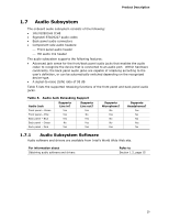
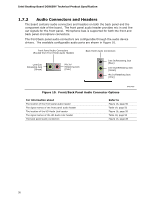
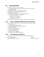
Intel Desktop Board DG965RY Technical Product Specification 1.5.2 USB The board supports up to 10 USB 2.0 ports, supports UHCI and EHCI, and uses UHCIand EHCI-compatible drivers. The ICH8 provides the USB controller for all ports. The port arrangement is as follows: • Six ports are implemented with stacked back panel connectors • Four ports are routed to two separate front panel USB headers NOTE Computer systems that have an unshielded cable attached to a USB port may not meet FCC Class B requirements, even if no device is attached to the cable. Use shielded cable that meets the requirements for full-speed devices. For information about The location of the USB connectors on the back panel The location of the front panel USB headers Refer to Figure 15, page 49 Figure 16, page 50 1.5.3 Serial ATA Interfaces The board provides four Serial ATA (SATA) connectors, which support one device per connector. 1.5.3.1 Serial ATA Support The ICH8's Serial ATA controller offers four independent Serial ATA ports with a theoretical maximum transfer rate of 3 Gbits/sec per port. One device can be installed on each port for a maximum of four Serial ATA devices. A point-to-point interface is used for host to device connections, unlike Parallel ATA IDE which supports a master/slave configuration and two devices per channel. For compatibility, the underlying Serial ATA functionality is transparent to the operating system. The Serial ATA controller can operate in both legacy and native modes. In legacy mode, standard IDE I/O and IRQ resources are assigned (IRQ 14 and 15). In Native mode, standard PCI Conventional bus resource steering is used. Native mode is the preferred mode for configurations using the Windows* XP and Windows 2000 operating systems. NOTE Many Serial ATA drives use new low-voltage power connectors and require adaptors or power supplies equipped with low-voltage power connectors. For more information, see: http://www.serialata.org/. For information about The location of the Serial ATA connectors Refer to Figure 16, page 50 26
-
 1
1 -
2
-
3
-
4
-
5
-
6
-
7
-
8
-
9
-
10
-
11
-
12
-
13
-
14
-
15
-
16
-
17
-
18
-
19
-
20
-
 21
21 -
 22
22 -
 23
23 -
 24
24 -
 25
25 -
 26
26 -
 27
27 -
 28
28 -
 29
29 -
 30
30 -
 31
31 -
32
-
33
-
34
-
35
-
36
-
37
-
38
-
39
-
40
-
41
-
42
-
43
-
44
-
45
-
46
-
47
-
48
-
49
-
50
-
51
-
52
-
53
-
54
-
55
-
56
-
57
-
58
-
59
-
60
-
61
-
62
-
63
-
64
-
65
-
66
-
67
-
68
-
69
-
70
-
71
-
72
-
73
-
74
-
75
-
76
-
77
-
78
-
79
-
80
-
81
-
82
-
83
-
84
-
85
-
86
-
87
-
88
-
89
-
90
-
91
-
92
 |
 |