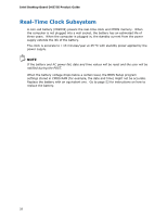
Intel DH57JG Product Guide - Page 27
Installing and Replacing Desktop Board Components, Before You Begin - i o shield
 |
View all Intel DH57JG manuals
Add to My Manuals
Save this manual to your list of manuals |
Page 27 highlights
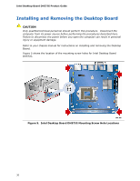
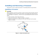
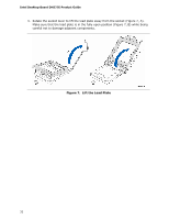
2 Installing and Replacing Desktop Board Components This chapter tells you how to: • Install the I/O shield • Install and remove the Desktop Board • Install and remove a processor • Install and remove memory • Install and remove a PCI Express x16 card • Connect Serial ATA cables • Connect to the internal headers • Connect to the audio system • Connect chassis fan and power supply cables • Set the BIOS configuration jumper • Clear passwords • Replace the battery Before You Begin CAUTION The procedures in this chapter assume familiarity with the general terminology associated with personal computers and with the safety practices and regulatory compliance required for using and modifying electronic equipment. Disconnect the computer from its power source and from any telecommunications links, networks, or modems before performing any of the procedures described in this chapter. Failure to disconnect power, telecommunications links, networks, or modems before you open the computer or perform any procedures can result in personal injury or equipment damage. Some circuitry on the board can continue to operate even though the front panel power button is off. NOTE Thermal Considerations Intel Desktop Board DH57JG supports Intel Core i5-600 series, and Core i3 processors up to 87 W TDP. The board also supports a discrete graphics card via the PCI Express x16 connector. Thermal considerations are important when choosing a suitable chassis for high end configurations. Refer to http://www.intel.com/go/miniitx for compatible mini-ITX chassis for Intel Desktop Board DH57JG. 27
-
 1
1 -
2
-
3
-
4
-
5
-
6
-
7
-
8
-
9
-
10
-
11
-
12
-
13
-
14
-
15
-
16
-
17
-
18
-
19
-
20
-
21
-
 22
22 -
 23
23 -
 24
24 -
 25
25 -
 26
26 -
 27
27 -
 28
28 -
 29
29 -
 30
30 -
 31
31 -
 32
32 -
33
-
34
-
35
-
36
-
37
-
38
-
39
-
40
-
41
-
42
-
43
-
44
-
45
-
46
-
47
-
48
-
49
-
50
-
51
-
52
-
53
-
54
-
55
-
56
-
57
-
58
-
59
-
60
-
61
-
62
-
63
-
64
-
65
-
66
-
67
-
68
-
69
-
70
-
71
-
72
-
73
-
74
-
75
-
76
-
77
-
78
 |
 |
