Intel DH57JG Product Guide - Page 35
Lower the Load Plate, Secure the Load Plate in Place, A.
 |
View all Intel DH57JG manuals
Add to My Manuals
Save this manual to your list of manuals |
Page 35 highlights
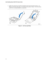
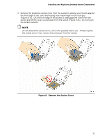
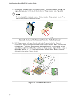
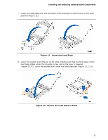
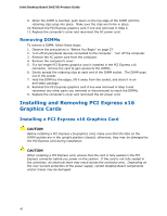
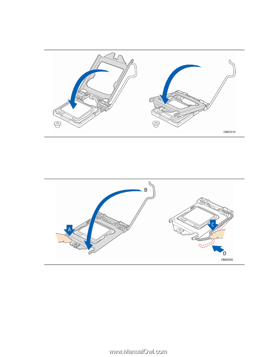
Installing and Replacing Desktop Board Components 7. Lower the load plate over the processor while leaving the socket lever in the open position (Figure 11). Figure 11. Lower the Load Plate 8. Lower the socket lever (Figure 12, B) while making sure that the front edge of the load plate slides under the shoulder screw cap as the lever is lowered (Figure 12, A). Latch the socket lever under the load plate tab (Figure 12, C, D). Figure 12. Secure the Load Plate in Place 35
-
 1
1 -
2
-
3
-
4
-
5
-
6
-
7
-
8
-
9
-
10
-
11
-
12
-
13
-
14
-
15
-
16
-
17
-
18
-
19
-
20
-
21
-
22
-
23
-
24
-
25
-
26
-
27
-
28
-
29
-
 30
30 -
 31
31 -
 32
32 -
 33
33 -
 34
34 -
 35
35 -
 36
36 -
 37
37 -
 38
38 -
 39
39 -
 40
40 -
41
-
42
-
43
-
44
-
45
-
46
-
47
-
48
-
49
-
50
-
51
-
52
-
53
-
54
-
55
-
56
-
57
-
58
-
59
-
60
-
61
-
62
-
63
-
64
-
65
-
66
-
67
-
68
-
69
-
70
-
71
-
72
-
73
-
74
-
75
-
76
-
77
-
78
 |
 |
Installing and Replacing Desktop Board Components
35
7.
Lower the load plate over the processor while leaving the socket lever in the open
position (Figure 11).
Figure 11.
Lower the Load Plate
8.
Lower the socket lever (Figure 12, B) while making sure that the front edge of the
load plate slides under the shoulder screw cap as the lever is lowered
(Figure 12, A).
Latch the socket lever under the load plate tab (Figure 12, C, D).
Figure 12.
Secure the Load Plate in Place