Intel DH57JG Product Guide - Page 47
Chassis Intrusion Header, Serial Header, S/PDIF Header
 |
View all Intel DH57JG manuals
Add to My Manuals
Save this manual to your list of manuals |
Page 47 highlights
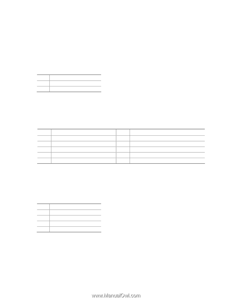
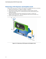
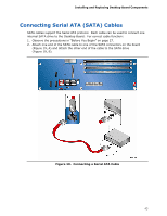
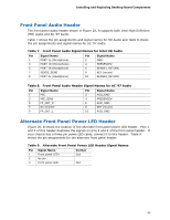
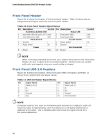
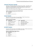
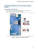
Installing and Replacing Desktop Board Components Chassis Intrusion Header Figure 20, E shows the location of the chassis intrusion header. This header can be connected to a mechanical switch on the chassis to detect if the chassis cover is removed. This switch should be in the open position when the chassis cover is installed and closed when the cover is removed. Table 12 shows the pin assignments and signal names for the chassis intrusion header. Table 12. Chassis Intrusion Header Signal Names Pin Description 1 Intruder# 2 Ground Serial Header Figure 20, F shows the location of the serial header. Table 13 shows the pin assignments and signal names for the serial header. Table 13. Serial Port Header Pin Signal Name 1 DCD (Data Carrier Detect) 3 TXD# (Transmit Data) 5 Ground 7 RTS (Request To Send) 9 RI (Ring Indicator) Pin Signal Name 2 RXD# (Receive Data) 4 DTR (Data Terminal Ready) 6 DSR (Data Set Ready) 8 CTS (Clear To Send) 10 Key (no pin) S/PDIF Header Figure 20, G shows the location of the S/PDIF output header. Table 14 shows the pin assignments and signal names for the S/PDIF output header. Table 14. S/PDIF Header Signal Names Pin Description 1 Ground 2 S/PDIF Out 3 Key (no pin) 4 +5 VDC 47
-
 1
1 -
2
-
3
-
4
-
5
-
6
-
7
-
8
-
9
-
10
-
11
-
12
-
13
-
14
-
15
-
16
-
17
-
18
-
19
-
20
-
21
-
22
-
23
-
24
-
25
-
26
-
27
-
28
-
29
-
30
-
31
-
32
-
33
-
34
-
35
-
36
-
37
-
38
-
39
-
40
-
41
-
 42
42 -
 43
43 -
 44
44 -
 45
45 -
 46
46 -
 47
47 -
 48
48 -
 49
49 -
 50
50 -
 51
51 -
 52
52 -
53
-
54
-
55
-
56
-
57
-
58
-
59
-
60
-
61
-
62
-
63
-
64
-
65
-
66
-
67
-
68
-
69
-
70
-
71
-
72
-
73
-
74
-
75
-
76
-
77
-
78
 |
 |