Intel DH57JG Product Guide - Page 45
Front Panel Audio Header, Alternate Front Panel Power LED Header
 |
View all Intel DH57JG manuals
Add to My Manuals
Save this manual to your list of manuals |
Page 45 highlights
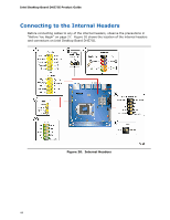
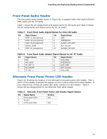
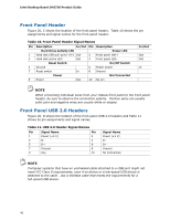
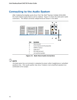
Installing and Replacing Desktop Board Components Front Panel Audio Header The front panel audio header shown in Figure 20, A supports both Intel High Definition (HD) Audio and AC '97 Audio. Table 7 shows the pin assignments and signal names for HD Audio and Table 8 shows the pin assignments and signal names for AC '97 Audio. Table 7. Front Panel Audio Signal Names for Intel HD Audio Pin Signal Name 1 PORT 1L (Microphone) 3 PORT 1R (Microphone) Pin Signal Name 2 GND 4 PRESENCE# 5 PORT 2R (Headphone) 6 SENSE1_RETURN 7 SENSE_SEND 9 PORT 2L (Headphone) 8 KEY (no pin) 10 SENSE2_RETURN Table 8. Front Panel Audio Header Signal Names for AC '97 Audio Pin Signal Name 1 MIC 3 MIC_BIAS 5 FP_OUT_R 7 No connect 9 FP_OUT_L Pin Signal Name 2 AUD_GND 4 PRESENCE# 6 AUD_GND 8 KEY (no pin) 10 AUD_GND Alternate Front Panel Power LED Header Figure 20, B shows the location of the alternate front panel power LED header. Pins 1 and 3 of this header duplicate the signals on pins 2 and 4 of the front panel header. If your chassis has a three-pin power LED cable, connect it to this header. Table 9 shows the pin assignments for the alternate front panel header. Table 9. Alternate Front Panel Power LED Header Signal Names Pin Signal Name 1 Front panel LED+ 2 No pin 3 Front panel LED- In/Out Out Out 45
-
 1
1 -
2
-
3
-
4
-
5
-
6
-
7
-
8
-
9
-
10
-
11
-
12
-
13
-
14
-
15
-
16
-
17
-
18
-
19
-
20
-
21
-
22
-
23
-
24
-
25
-
26
-
27
-
28
-
29
-
30
-
31
-
32
-
33
-
34
-
35
-
36
-
37
-
38
-
39
-
 40
40 -
 41
41 -
 42
42 -
 43
43 -
 44
44 -
 45
45 -
 46
46 -
 47
47 -
 48
48 -
 49
49 -
 50
50 -
51
-
52
-
53
-
54
-
55
-
56
-
57
-
58
-
59
-
60
-
61
-
62
-
63
-
64
-
65
-
66
-
67
-
68
-
69
-
70
-
71
-
72
-
73
-
74
-
75
-
76
-
77
-
78
 |
 |
