Intel DX79TO Product Guide - Page 7

Installing a Fan Heat Sink and Connecting the Cable to - desktop board

Page 7 highlights

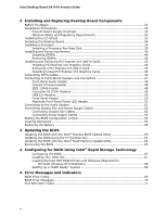
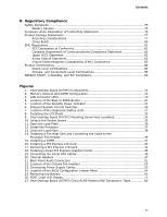
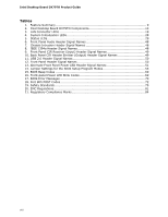
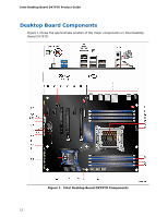
Contents B Regulatory Compliance Safety Standards 75 Battery Caution 75 European Union Declaration of Conformity Statement 76 Product Ecology Statements 77 Recycling Considerations 77 China RoHS 80 EMC Regulations 81 FCC Declaration of Conformity 81 Canadian Department of Communications Compliance Statement 82 Japan VCCI Statement 82 Korea Class B Statement 83 Ensure Electromagnetic Compatibility (EMC) Compliance 83 Product Certifications 84 Board-Level Certifications 84 Chassis- and Component-Level Certifications 85 ENERGY STAR*, e-Standby, and ErP Compliance 85 Figures 1. Intel Desktop Board DX79TO Components 12 2. Memory Channel and DIMM Configuration 16 3. LAN Connector LEDs 19 4. Location of the Back to BIOS Button 21 5. Location of the Standby Power Indicator 24 6. Onboard System Control Switches 26 7. Location of the Diagnostic/Status LEDs 27 8. Installing the I/O Shield 33 9. Intel Desktop Board DX79TO Mounting Screw Hole Locations 34 10. Unlatch the Socket Levers 35 11. Open the Load Plate 36 12. Install the Processor 37 13. Close the Load Plate 38 14. Installing a Fan Heat Sink and Connecting the Cable to the Processor Fan Header 39 15. Installing a DIMM 41 16. Installing a PCI Express x16 Card 43 17. Removing a PCI Express x16 Card 44 18. Installing Linked PCI Express Graphics Cards 45 19. Connecting the Serial ATA Cables 46 20. Internal Headers 47 21. Back Panel Audio Connectors 51 22. Location of the Chassis Fan Headers 52 23. Connecting Power Supply Cables 53 24. Location of the BIOS Configuration Jumper Block 54 25. Removing the Battery 61 26. POST Code LED Display 71 27. Intel Desktop Board DX79TO China RoHS Material Self Declaration Table 80 vii

  • 1
  • 2
  • 3
  • 4
  • 5
  • 6
  • 7
  • 8
  • 9
  • 10
  • 11
  • 12
  • 13
  • 14
  • 15
  • 16
  • 17
  • 18
  • 19
  • 20
  • 21
  • 22
  • 23
  • 24
  • 25
  • 26
  • 27
  • 28
  • 29
  • 30
  • 31
  • 32
  • 33
  • 34
  • 35
  • 36
  • 37
  • 38
  • 39
  • 40
  • 41
  • 42
  • 43
  • 44
  • 45
  • 46
  • 47
  • 48
  • 49
  • 50
  • 51
  • 52
  • 53
  • 54
  • 55
  • 56
  • 57
  • 58
  • 59
  • 60
  • 61
  • 62
  • 63
  • 64
  • 65
  • 66
  • 67
  • 68
  • 69
  • 70
  • 71
  • 72
  • 73
  • 74
  • 75
  • 76
  • 77
  • 78
  • 79
  • 80
  • 81
  • 82
  • 83
  • 84
  • 85
  • 86

Contents
vii
B
Regulatory Compliance
Safety Standards
...............................................................................................
75
Battery Caution
..........................................................................................
75
European Union Declaration of Conformity Statement
..............................................
76
Product Ecology Statements
................................................................................
77
Recycling Considerations
.............................................................................
77
China RoHS
...............................................................................................
80
EMC Regulations
................................................................................................
81
FCC Declaration of Conformity
......................................................................
81
Canadian Department of Communications Compliance Statement
......................
82
Japan VCCI Statement
................................................................................
82
Korea Class B Statement
.............................................................................
83
Ensure Electromagnetic Compatibility (EMC) Compliance
..................................
83
Product Certifications
..........................................................................................
84
Board-Level Certifications
............................................................................
84
Chassis- and Component-Level Certifications
..................................................
85
ENERGY STAR*, e-Standby, and ErP Compliance
....................................................
85
Figures
1. Intel Desktop Board DX79TO Components
........................................................
12
2. Memory Channel and DIMM Configuration
........................................................
16
3. LAN Connector LEDs
.....................................................................................
19
4.
Location of the Back to BIOS Button
................................................................
21
5.
Location of the Standby Power Indicator
..........................................................
24
6. Onboard System Control Switches
..................................................................
26
7. Location of the Diagnostic/Status LEDs
............................................................
27
8. Installing the I/O Shield
................................................................................
33
9.
Intel Desktop Board DX79TO Mounting Screw Hole Locations
..............................
34
10. Unlatch the Socket Levers
.............................................................................
35
11. Open the Load Plate
......................................................................................
36
12. Install the Processor
.....................................................................................
37
13. Close the Load Plate
.....................................................................................
38
14. Installing a Fan Heat Sink and Connecting the Cable to the
Processor Fan Header
....................................................................................
39
15. Installing a DIMM
.........................................................................................
41
16. Installing a PCI Express x16 Card
...................................................................
43
17. Removing a PCI Express x16 Card
..................................................................
44
18. Installing Linked PCI Express Graphics Cards
....................................................
45
19. Connecting the Serial ATA Cables
....................................................................
46
20. Internal Headers
..........................................................................................
47
21. Back Panel Audio Connectors
.........................................................................
51
22. Location of the Chassis Fan Headers
................................................................
52
23. Connecting Power Supply Cables
....................................................................
53
24. Location of the BIOS Configuration Jumper Block
..............................................
54
25. Removing the Battery
...................................................................................
61
26. POST Code LED Display
.................................................................................
71
27. Intel Desktop Board DX79TO China RoHS Material Self Declaration Table
..............
80