Intel E3300 Data Sheet - Page 98
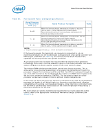
Table 30., Fan Heatsink Power and Signal Specifications
 |
View all Intel E3300 manuals
Add to My Manuals
Save this manual to your list of manuals |
Page 98 highlights
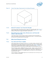
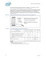
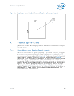
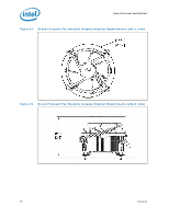
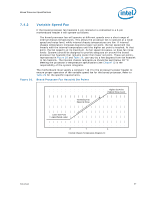
Boxed Processor Specifications Table 30. Fan Heatsink Power and Signal Specifications Boxed Processor Fan Heatsink Set Point (°C) Boxed Processor Fan Speed Notes X 30 When the internal chassis temperature is below or equal to this set point, the fan operates at its lowest speed. 1 Recommended maximum internal chassis temperature for nominal operating environment. Y = 35 When the internal chassis temperature is at this point, the fan operates between its lowest and highest speeds. Recommended maximum internal chassis temperature for - worst-case operating environment. Z 38 When the internal chassis temperature is above or equal to this set point, the fan operates at its highest speed. - NOTES: 1. Set point variance is approximately ± 1 C from fan heatsink to fan heatsink. If the boxed processor fan heatsink 4-pin connector is connected to a 4-pin motherboard header and the motherboard is designed with a fan speed controller with PWM output (CONTROL see Table 29) and remote thermal diode measurement capability the boxed processor will operate as follows: As processor power has increased the required thermal solutions have generated increasingly more noise. Intel has added an option to the boxed processor that allows system integrators to have a quieter system in the most common usage. The 4th wire PWM solution provides better control over chassis acoustics. This is achieved by more accurate measurement of processor die temperature through the processor's Digital Thermal Sensors (DTS) and PECI. Fan RPM is modulated through the use of an ASIC located on the motherboard that sends out a PWM control signal to the 4th pin of the connector labeled as CONTROL. The fan speed is based on actual processor temperature instead of internal ambient chassis temperatures. If the new 4-pin active fan heat sink solution is connected to an older 3-pin baseboard processor fan header, it will default back to a thermistor controlled mode, allowing compatibility with existing 3-pin baseboard designs. Under thermistor controlled mode, the fan RPM is automatically varied based on the Tinlet temperature measured by a thermistor located at the fan inlet. For more details on specific motherboard requirements for 4-wire based fan speed control, refer to the appropriate Thermal and Mechanical Design Guidelines (see Section 1.2). § 98 Datasheet
-
 1
1 -
2
-
3
-
4
-
5
-
6
-
7
-
8
-
9
-
10
-
11
-
12
-
13
-
14
-
15
-
16
-
17
-
18
-
19
-
20
-
21
-
22
-
23
-
24
-
25
-
26
-
27
-
28
-
29
-
30
-
31
-
32
-
33
-
34
-
35
-
36
-
37
-
38
-
39
-
40
-
41
-
42
-
43
-
44
-
45
-
46
-
47
-
48
-
49
-
50
-
51
-
52
-
53
-
54
-
55
-
56
-
57
-
58
-
59
-
60
-
61
-
62
-
63
-
64
-
65
-
66
-
67
-
68
-
69
-
70
-
71
-
72
-
73
-
74
-
75
-
76
-
77
-
78
-
79
-
80
-
81
-
82
-
83
-
84
-
85
-
86
-
87
-
88
-
89
-
90
-
91
-
92
-
 93
93 -
 94
94 -
 95
95 -
 96
96 -
 97
97 -
 98
98 -
 99
99 -
 100
100
 |
 |
