Intel S5000VCL User Guide - Page 34
Clearing the CMOS - ram
 |
UPC - 735858183000
View all Intel S5000VCL manuals
Add to My Manuals
Save this manual to your list of manuals |
Page 34 highlights
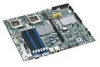
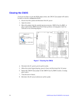
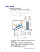
Clearing the CMOS If you are not able to access the BIOS setup screens, the CMOS Clear jumper will need to be used to reset the configuration RAM. 1. Power down the system and disconnect the AC power. 2. Open the server. 3. Move the jumper from the normal operation position, CMOS Clear by BMC, at pins 1 and 2 to the CMOS Clear Force Erase position, covering pins 2 and 3 as indicated in the following diagram. CMOS CLR J1C2 3 1-2: Normal Operation (Default) 2-3: CLEAR CMOS 3 Figure 7. Clearing the CMOS AF000658 4. Reconnect the AC power, power up the system. 5. When the system begins beeping, power it down and disconnect the AC power. 6. Return the CMOS Clear jumper to the CMOS Clear by BMC location, covering pins 1 and 2. 7. Close the server chassis. 8. Reconnect the AC power and power up the system. 16 Intel® Server Board S5000VCL User Guide
-
 1
1 -
2
-
3
-
4
-
5
-
6
-
7
-
8
-
9
-
10
-
11
-
12
-
13
-
14
-
15
-
16
-
17
-
18
-
19
-
20
-
21
-
22
-
23
-
24
-
25
-
26
-
27
-
28
-
 29
29 -
 30
30 -
 31
31 -
 32
32 -
 33
33 -
 34
34 -
 35
35 -
 36
36 -
 37
37 -
 38
38 -
 39
39 -
40
-
41
-
42
-
43
-
44
-
45
-
46
-
47
-
48
-
49
-
50
-
51
-
52
-
53
-
54
-
55
-
56
-
57
-
58
-
59
-
60
-
61
-
62
-
63
-
64
-
65
-
66
-
67
-
68
 |
 |
